be achieved if the power supply delivers higher current, up to a maximum in accordance
with Table: Logic in
terface technical data.
If the facility to adjust the power limit seng is not available, use a power supply
capable of delivering enough current to meet the Edwards factory default power limit
seng, shown in Table: Logic interface technical data.
4.9 Logic interface connector
nEXT pumps have a 15-way logic interface connector on the end of the logic interface
cable. Use a suitable connector mang half (not supplied) to connect the nEXT pump to
the customer equipment. Refer to the following table for the connector mang half
type.
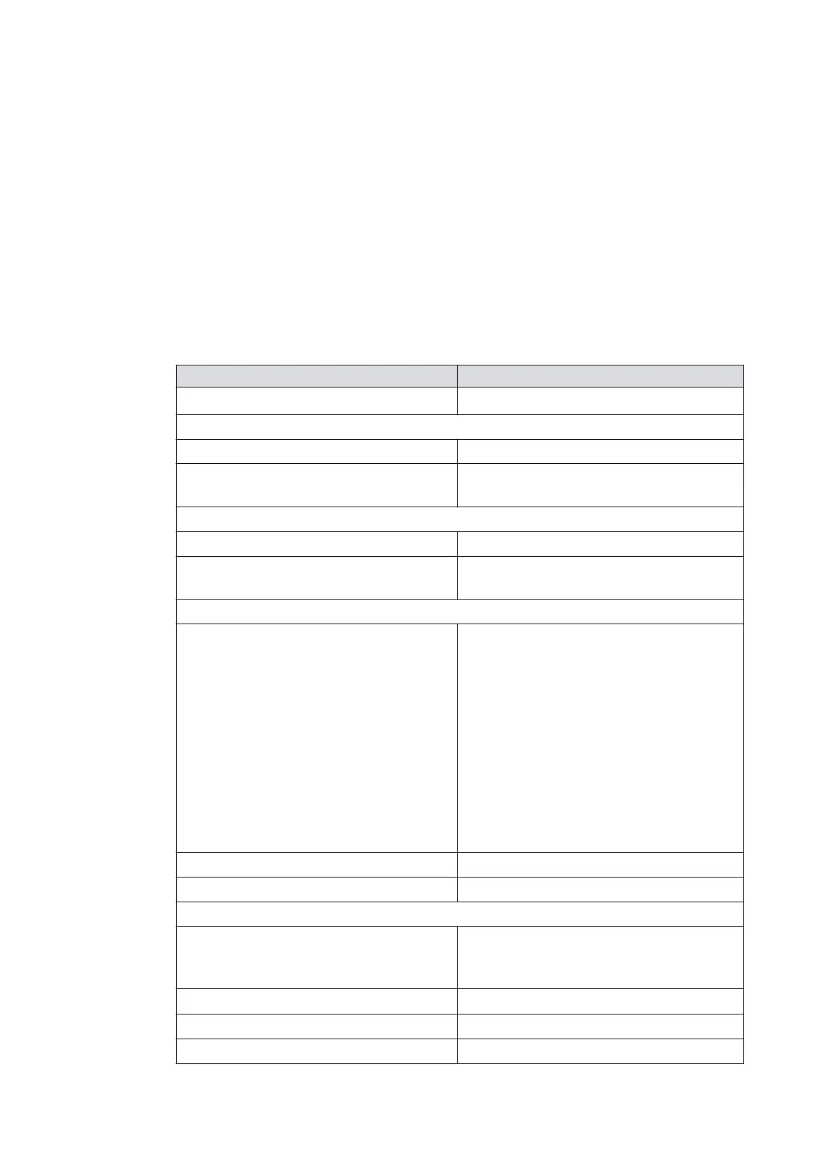
Table 10
Logic interface technical data
Logic interface item
Connector
*
15‑way D‑type male
Start and serial enable control inputs:
Enabled control voltage: low (close) 0 to 0.8 V d.c. (Iout = 0.55 mA nominal)
Disabled control voltage: high (open) 4 to 26.4 V d.c. (internal pull up to 6.4 V
nominal)
Standby control input:
Enabled control voltage: low (close) 0 to 0.8 V d.c. (Iout = 0.29 mA nominal)
Disabled control voltage: high (open) 4 to 26.4 V d.c. (internal pull up to 3.2 V
nominal)
Analogue output:
Output voltage 0 to 10 V d.c. (directly proporonal t
o
measured parameter)
Motor speed: 0 ‑ 820 Hz (0‑100%) for
nEXT730/930D,
0 ‑ 700 Hz (0‑100%) for nEXT1230H
Motor power: 0 ‑ 500 W for
nEXT730/930D,
0 ‑ 660 W for nEXT1230H
Motor temperature: 0 ‑ 100 °C
Controller temperature: 0 ‑ 100 °C
Bearing temperature: 0 ‑ 100 °C
Voltage accuracy ± 0.2 V
Output current
£ 5 mA for specied accur
acy
Normal status output:
Type Open collector transistor plus pull up resis-
tor. Refer to Figure: Interface circuits for
nEXT turbo pump controllers
< Normal speed (default 80%)
O (2.2 kW pull up to 12 V d.c.)
³
Normal speed
On (< 0.8 V d.c. sinking 20 mA)
Current rang 20 mA t
o 0 V
08/2021 - ©Edwards Limited
Page 35B8J200880_D
300812671_002_C3
B8J200880_D - Technical data