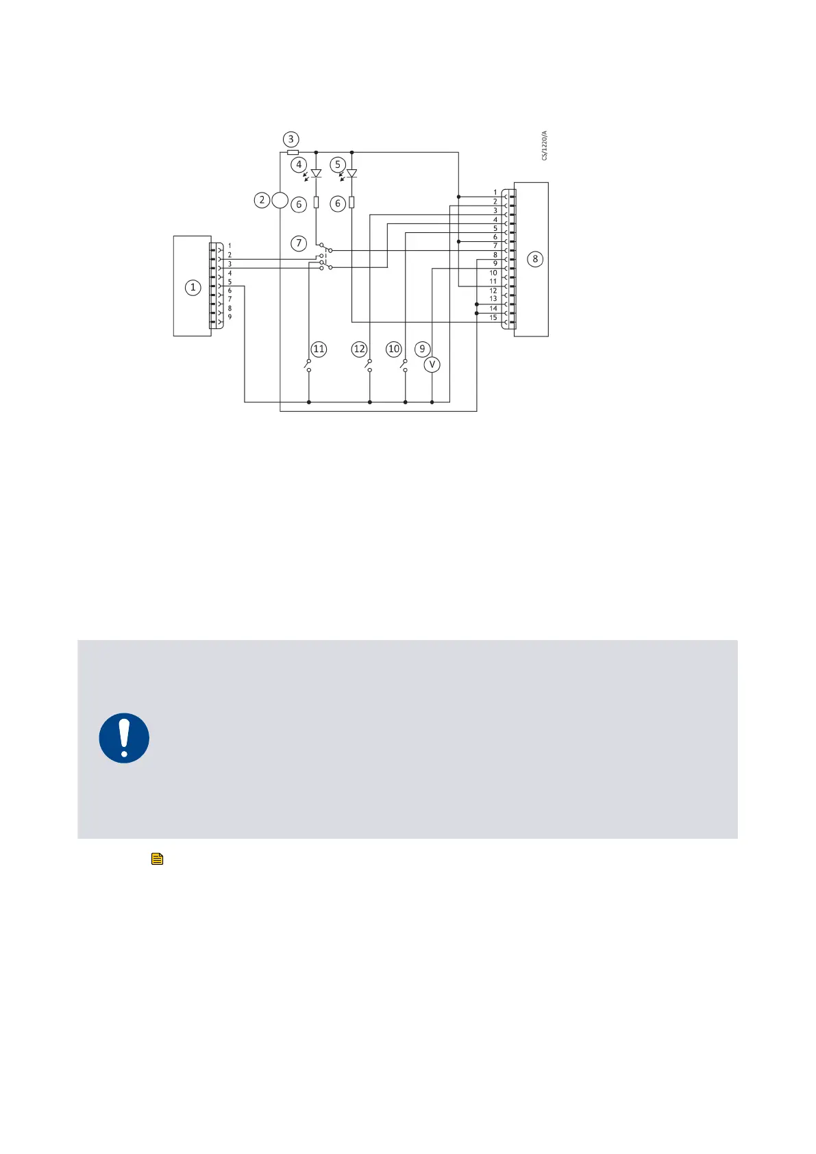
Figure 25 Logic interface connecon - mix
ed parallel and serial operaon
1. RS232 interface on control equipment 2. Oponal 24 V d.c. electric
al supply
3. F
use 4. Oponal LED indicator - system OK
5. Oponal LED indicator - normal speed 6. Current limit resistor for LED
7. Oponal serial link selector 8. nEXT pump
9. Oponal voltmeter 10. Oponal serial enable switch
11. Oponal standby switch 12. Start switch
1. RS232 interface on control equipment 2. Oponal 24 V d.c. electrical supply
3. Fuse 4. Oponal LED indicator - system OK
5. Oponal LED indicator - normal speed 6. Current limit resistor for LED
7. Oponal serial link selector 8. nEXT pump
9. Oponal voltmeter 10. Oponal serial enable switch
11. Oponal standby switch 12. Start switch
5.8 Cooling
5.8.1 Cooling requirements
NOTICE:
Ensur
e tha
t the pump is adequately cooled to prevent damage to the rotor and
bearing.
When using alternave cooling arrangements other than the standard Edwards
cooling accessories, ensure cooling is not solely directed or ducted onto the pump
controller.
If the pump will be located inside an enclosure, ensure that there is adequate
venlaon so that the ambient temperature around the pump does not exceed 40 °C.
Note:
During operaon, if the t
emperature of an
y surface of the pump is higher than 50 °C, the
cooling is inadequate and should be increased. Pump performance may be aected if you
do not cool the pump and nEXT motor controller adequately.
Edwards recommends that, wherever possible, the pump is cooled by forced air cooling
or water cooling.
Select the cooling type required according to the ambient temperature:
08/2021 - ©Edwards Limited
Page 63B8J200880_D
300812671_002_C3
B8J200880_D - Inst
allaon