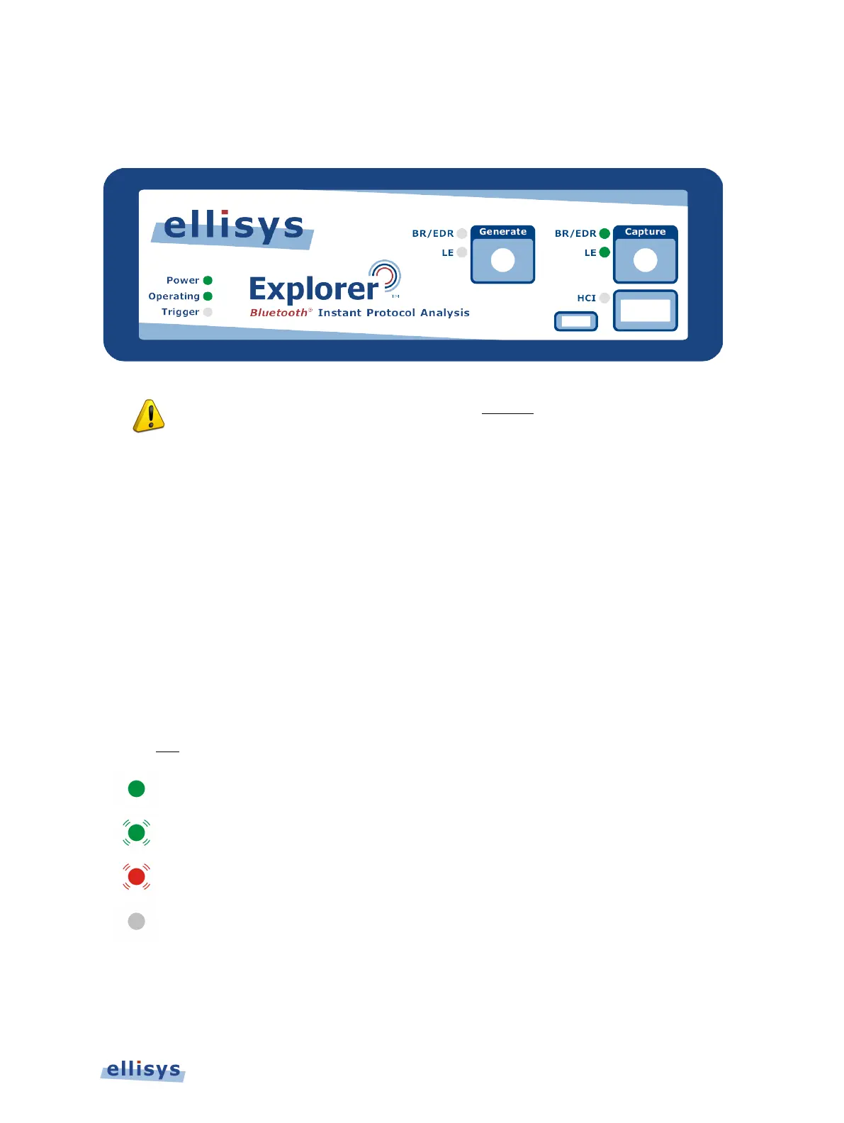
2.3 Front Panel Overview
The front panel of the Bluetooth Explorer 400 Analyzer is shown below:
attaching an antenna to the front panel, DO NOT over tighten. Screw on
antenna to a light finger-tight torque only.
Capture Connector
The (Standard SMA) Capture connector is used to connect the antenna (supplied) for capture of
BR/EDR and LE traffic.
Generate Connector
The (Standard SMA) Generate connector is for future implementations (not currently used).
HCI Connectors
The HCI connectors (USB 2.0 Standard-A and Micro-B) are used for USB HCI traffic capture.
Power LED
The Power LED indicates if the unit is correctly powered from the supplied 12VDC/2A power
adapter and connected to the control computer (with USB driver installed).
DC-powered and USB-connected, ready to operate.
DC-powered but not USB-connected.
USB-connected but not DC-powered.
Not DC-powered and not USB-connected. The Power LED may also be off if
when the unit is in power
-saving mode after the control computer has been
Installing the Application | 17 of 201