Generate LE LED
Reserved for future implementation.
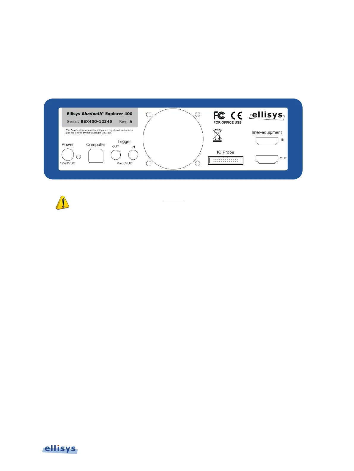
2.4 Back Panel Overview
The back panel of the Bluetooth Explorer 400 Analyzer is shown below:
When connecting the USB cable
DO NOT force the connector into the unit. The
metal part of the connector should not be inserted completely into the
connection port. Forcing the conne
ctor or inserting all of the metal part of the
connector will break the port connection and is not covered by the warranty.
Power
DC jack power input. The adjacent LED illuminates constant green if a correct voltage is
applied, and illuminates constant red if the voltage is applied reversed.
Accepted Voltage Range: 12VDC to 24VDC.
Minimum Power: 18W
Computer
Type B USB 2.0 receptacle. Attaches to the control computer.
Trigger OUT
SMA connector used for sending TTL voltage level shift or pulse to external equipment.
Trigger IN
SMA connector used for accepting TTL voltage level shift or pulse from external equipment.
IO Probe
Integrated logic analyzer probe for capturing UART and SPI HCI traffic, Audio I2S signals, WCI-
2 traffic, and logic signals. A flying-leads adapter cable is supplied when these options are
included with purchase. See Appendix A – Flying Leads Cable for details.
Installing the Application | 19 of 201