Appendix A – Flying Leads Cable
The Flying Leads Cable connects the IO Probe connector (located on the analyzer’s back panel)
to one or more external HCI, WCI-2, Audio I2S, or logic implementations. This traffic will be
captured concurrently with through-the-air traffic and will be displayed in the respective
Overviews and other views as applicable (e.g., the Instant Timing View).
The IO Probe connector contains 26 pins (two rows of 13 pins), which mate with sockets on the
mating connector of the Flying Leads Cable. Spacing is 1.27 x 1.27mm. Color-coded flying
lead sockets will mate with pins from the user’s HCI and/or logic implementation.
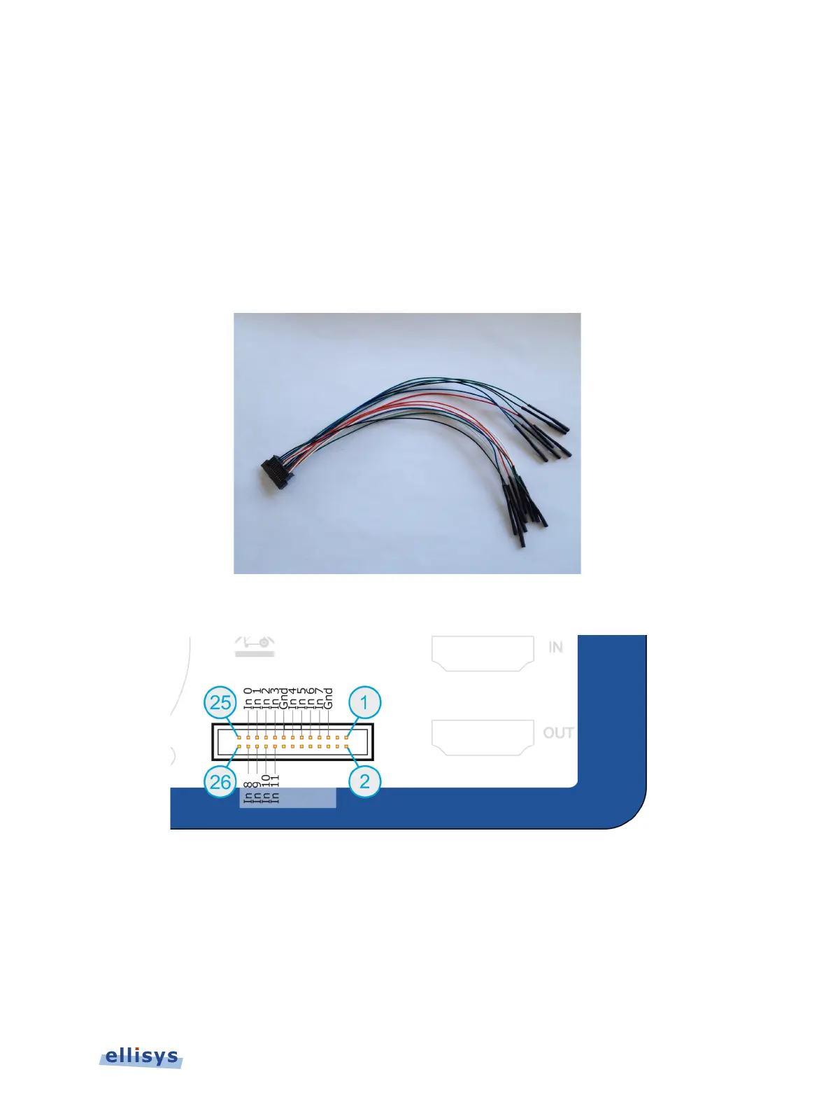
Flying Leads Cable
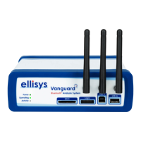
Pinout for IO Probe Connector
On the Flying Leads Cable, Inputs 0 and 1 are used for the primary UART capture, Inputs 2 and
3 are used for the secondary UART capture, and Inputs 4 and 5 are used for the WCI-2 capture.
Use GND as shown. For UART, signal lines (Inputs 0,1 and 2,3) may be reversed, as the
analyzer will auto-detect the polarity.
Appendix A – Flying Leads Cable | 195 of 201