C4 Maintenance 16. Calibration
166 C Series Maintenance Manual Rev.2
After resetting the error, the motor encoder of the joint whose parts have been replaced
will be initialized.
Set the jog mode to “Joint” in [Jog & Teach] and operate the Manipulator in jog motion
to match the home position marks (0 pulse position) of the joint accurately.
When the joint cannot move to the home position, operate the Manipulator to match the
tram mark placed in
Setup & Operation 3.7 Checking the Basic Orientation
Initialize the encoder when the joint matches the home position or the tram mark.
For the encoder initialization, refer to the procedure indicated above.
When the origin of the Joint #5 is calibrated, the Joint #6 will be out of position.
(Due
to the structure of the Manipulator, any offset in the position of the Joint #5 affects the
Joint #6.)
Calibrate the origin of the Joint #6 together when calibrating
the Joint #5.
.
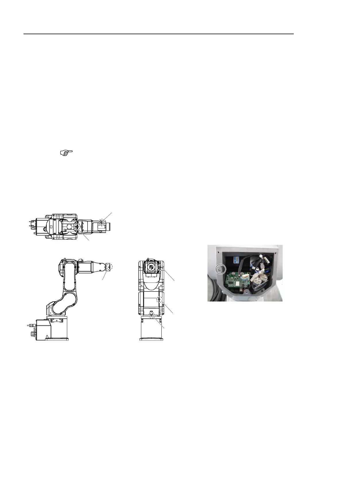
Position of grooves for calibration
The key is secured to the inside of the
Arm #1 center cover using M4 screw.
Hexagon socket head cap bolts:
M3×6
Be sure to put the key back to the
original position after use.
Position of the calibration key
-1 Prepare the calibration key.
A calibration key is secured inside the Arm #1 center cover using the M4 screw.
careful not to lose the screw.