C8 Maintenance 4. Cable Unit
256 C Series Maintenance Manual Rev.2
Connect the M/C cable connectors.
Connectors: X11, X12, X14, BR010, BR011, X010, X020,
X040, LED, GS01, BT1
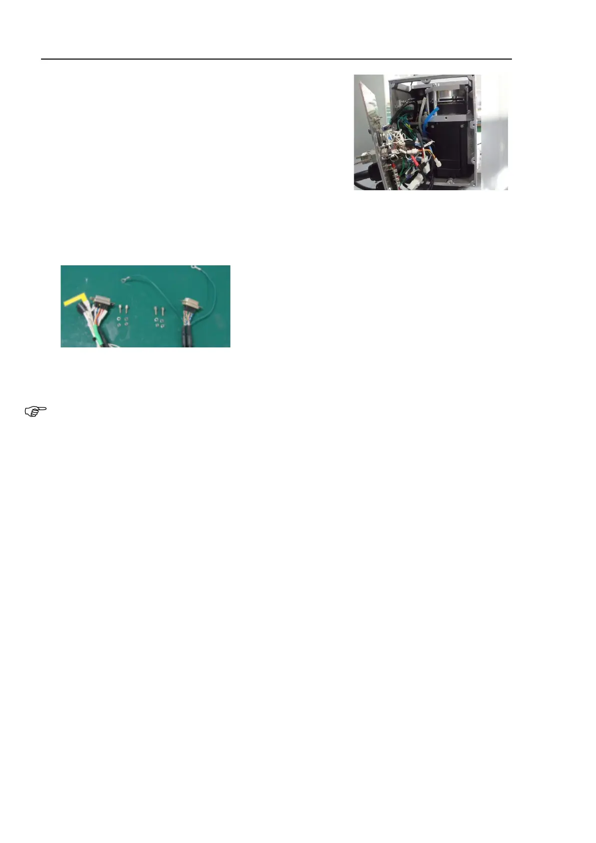
Install the D-sub connectors according to the marks on the connector plate.
Left: D-sub connector for brake release (with a wire marker: SW1): B-release
Right: D-sub connector for user wiring (without a wire marker: With round terminal): D-sub
Install the two air tubes according to the marks on the connector plate.
Air1: Clear
Air2: Blue
Install the air tube with the correct color.
Install the covers and plate indicated below.
Arm #4 side covers (both sides) Arm #4 maintenance cover (C8XL only)
Arm #3 cover Arm #3 maintenance cover
Arm #2 side covers (both sides) Arm #1 side covers (both sides)
Arm #1 center cover Base maintenance cover
Connector plate (M/C cable backward)
For details, refer to C8 Maintenance: 3. Covers.
Perform calibration.
For details, refer to C8 Maintenance: 16. Calibration.