C8 Maintenance 4. Cable Unit
C Series Maintenance Manual Rev.2 255
Install the Joint #1 motor unit.
For details, refer to C8 Maintenance: 5.1.1 Joint #1 - Replacing the Motor (M/C Cable Backward),
Installation steps (1) to (4).
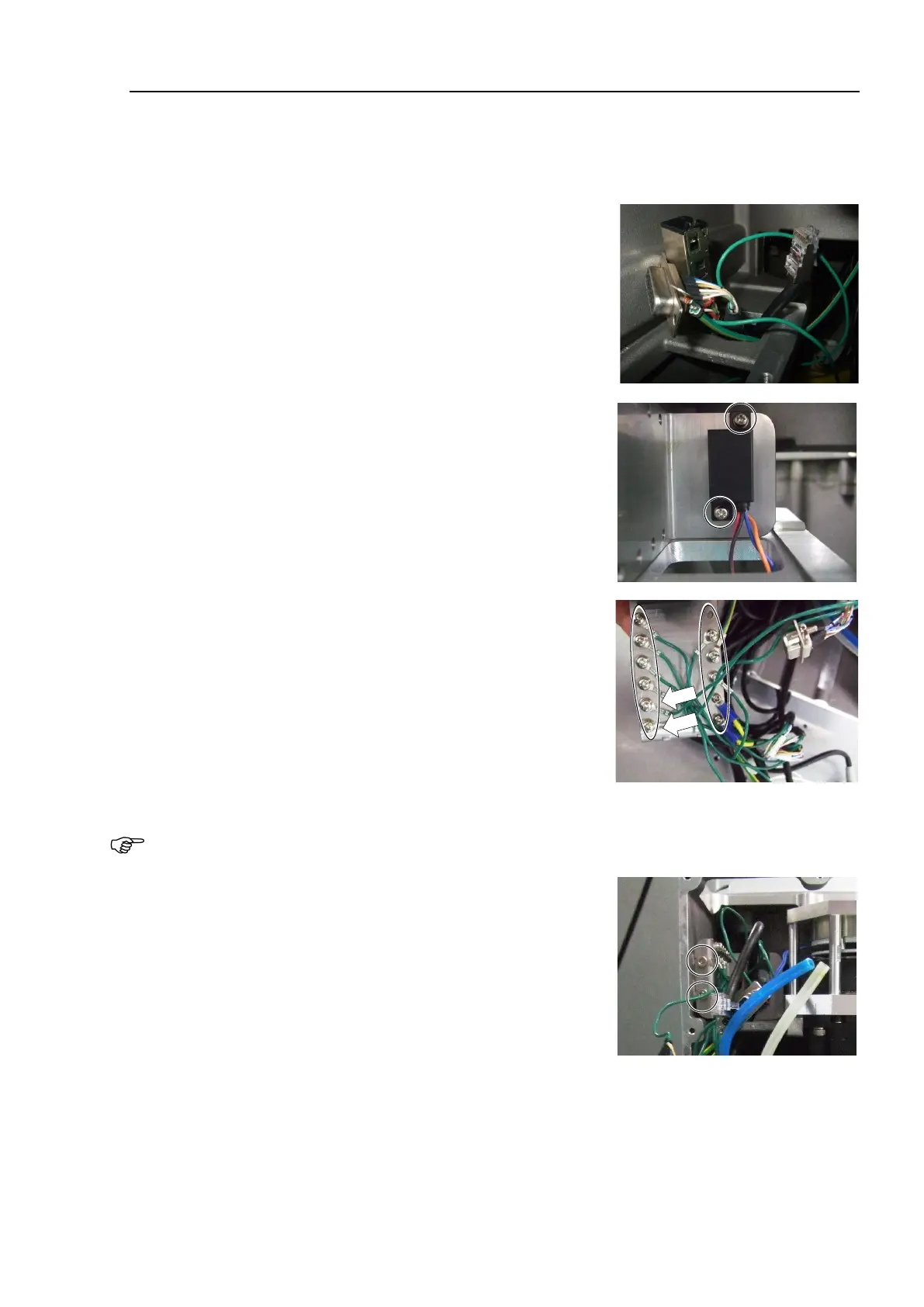
Push out the following cables upward through the opening of the
base.
D-sub cable
Ground wire
RJ45 connector
F-sensor connector
Install the brake power supply to the plate.
The cables should be located in the direction as shown in the photo.
(See the photo.)
Cross recessed head screws with washer: 2-M3×6
Tightening torque: 0.45 ± 0.1 N·m
Install the ground wire terminals to the plate.
Cross recessed head screws with washer
S, C models :9-M4×8, 2-M3×6
P model :10-M4×8, 2-M3×6
Tightening torque :0.9 ± 0.1 N·m (M4×8)
0.45 ± 0.1 N·m (M3×6)
The installation positions of the D-sub cable ground terminals are predetermined.
them to the two screw holes on the backside of the Manipulator (indicated with arrows in the photo).
Install the ground wire plate (M/C cable backward).
Hexagon socket head cap bolts: 2-M4×10
Tightening torque: 4.0 ± 0.2 N·m
Install the following connectors according to the marks on the connector plate.
RJ45 connector: Ether
F-sensor connector: F-sensor

 Loading...


