C8 Maintenance 4. Cable Unit
260 C Series Maintenance Manual Rev.2
Installation: Cable unit (M/C cable downward)
1. Perform the installation steps (1) to (62) of
C8 Maintenance: 4.1.1 Replacing the Cable Unit (M/C Cable Backward).
2. Turn the Manipulator laterally.
CAUTION
■
When turning the Manipulator laterally, there must be two or more people to work
on it so that at least one of them can support the arm while the
others are removing
Removing the bolts without supporting the arm may result in the arm f
alling, bodily
injury, and/or malfunction of the robot system.
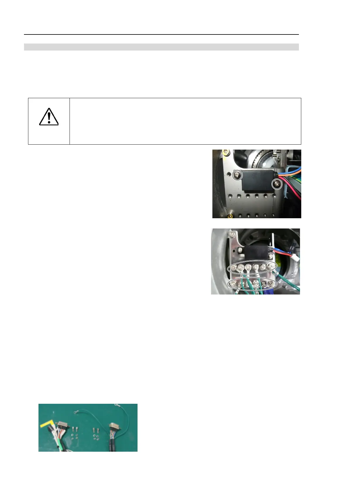
3. Install the brake power supply to the plate.
The cables should be located in the direction as shown in the photo.
(See the photo.)
Cross recessed head screws with washer: 2-M3×6
Tightening torque: 0.45 ± 0.1 N·m
4. Install the ground wire terminals to the plate.
Cross recessed head screws with washer
S, C models: : 9-M4×8, 2-M3×6
P model : 10-M4×8, 2-M3×6
Tightening torque : 0.9 ± 0.1 N·m (M4×8)
0.45 ± 0.1 N·m (M3×6)
5. Install the following connectors according to the marks on the connector plate.
RJ45 connector: Ether
F-sensor connector: F-sensor
6. Connect the M/C cable connectors.
Connectors: X11, X12, X14, BR010, BR011, X010, X020, X040, LED, GS01, BT1
7. Install the D-sub connectors according to the marks on the connector plate.
Left: D-sub connector for brake release (with a wire marker: SW1): B-release
Right: D-sub connector for user wiring (without a wire marker: With round terminal): D-sub