C8 Maintenance 5. Joint #1
284 C Series Maintenance Manual Rev.2
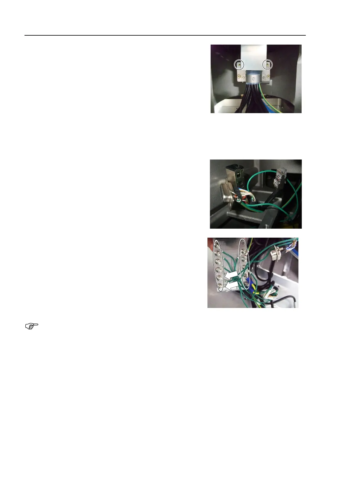
10. Install the cable interference prevention plate.
Hexagon socket head cap bolts: 2-M3×6
Tightening torque: 2.0 ± 0.1 N·m
11. Install the Joint #1 motor unit.
For details, refer to C8 Maintenance 5.1.1 Joint #1 – Replacing the Motor (M/C Cable Backward),
Removal steps (1) to (4).
12.
Pass the following parts through the hole inside the base to the
upper part of the base.
D-sub cable
Ground wire
RJ45 connector
F-sensor connector
13. Connect the ground wires.
Cross recessed head screws with washer
S, C models : 9-M4×8, 2-M3×6
P model : 10-M4×8, 2-M3×6
Tightening torque : 0.9 ± 0.1N·m (M4×8)
0.45 ± 0.1 N·m (M3×6)
The ground terminals of the D-sub cables have fixed installation positions. Install them to the two
screw holes. (Photo: indicated by the arrows).
14. Install the following parts.
Connector plate
Connector
Cable grounding plate
Brake power supply
For details, refer to C8 Maintenance 5.1.3 Joint #1 – Replacing the Timing Belt (M/C Cable Backward),
Installation steps (6) to (14).