C8 Maintenance 6. Joint #2
312 C Series Maintenance Manual Rev.2
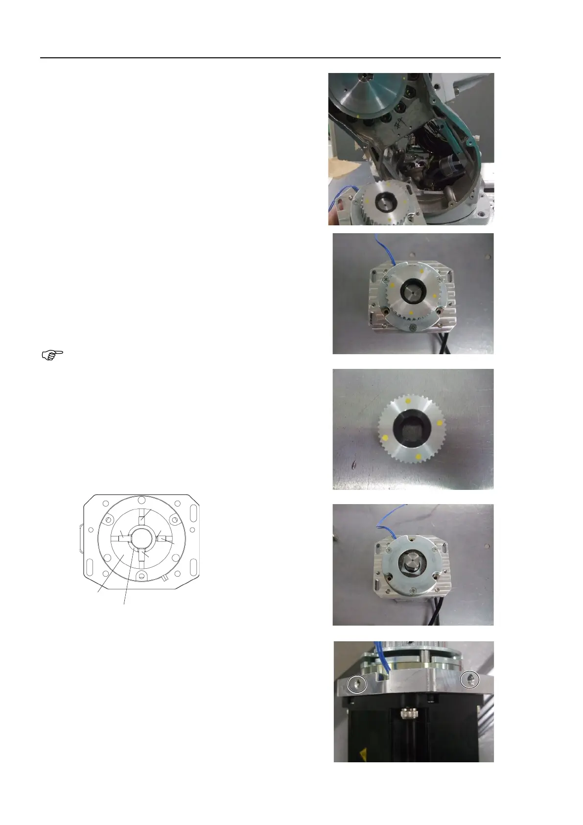
9. Remove the Joint #2 motor unit.
10. Remove the Joint #2 pulley 1 and the drive boss from the
motor shaft of the Joint #2 motor unit.
Remove two screws at the flat (D-cut) part of the motor
shaft when viewing from above. (A in the figure)
Pulley and the motor shaft (A)
Hexagon socket set screws: 2-M5×12
Do not remove the pulley and drive boss screws (B in the
figure). There is a brass bushing on one of the set screws.
If you removed the screws (B), be careful not to lose the
brass bushing.
A: Pulley and motor shaft screws
(D-cut part of the motor shaft × 2)
B: Pulley and drive boss screws
Do not remove these screws.
C: Bushing
Pulley
Drive boss
A
A
C
B
B
11. Remove the Joint #2 electromagnetic brake.
Hexagon socket set screws: 2-M6×6 (with a brass bushing)