Rev. A Disassembly, Assembly, and Adjustments 5-13
TM-U950/U950P Technical Manual
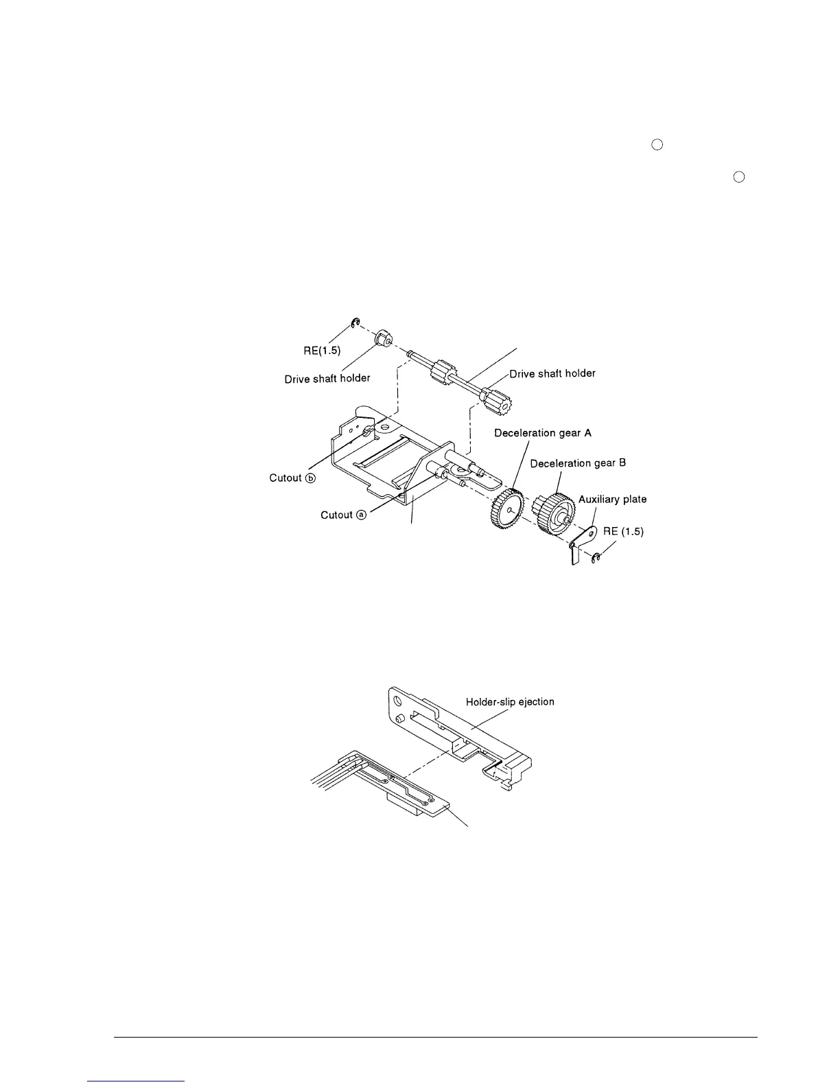
Sub-assembly F: Cutter Frame Assembly
1.* Fit the drive shaft holder of the cutter drive shaft sub-assembly into cutout .
2.* Pass the drive shaft holder onto the cutter drive shaft sub-assembly and fit it into cutout .
Then attach the RE.
3.* Attach the deceleration gear B to the cutter frame sub-assembly shaft.
4.* Attach the deceleration gear A to the cutter frame sub-assembly shaft.
5. Mount the auxiliary plate to the cutter frame sub-assembly shaft and secure it with the RE.
Sub-assembly G: Detector-Slip Ejection Assembly
1. Push the detector-slip ejection sub-assembly into the holder-slip ejection.
a
b
Cutter drive shaft sub-assembly
Cutter frame sub-assembly
Detector-slip ejection sub-assembly
CONFIDENTIAL