Rev. A Disassembly, Assembly, and Adjustments 5-75
TM-U950/U950P Technical Manual
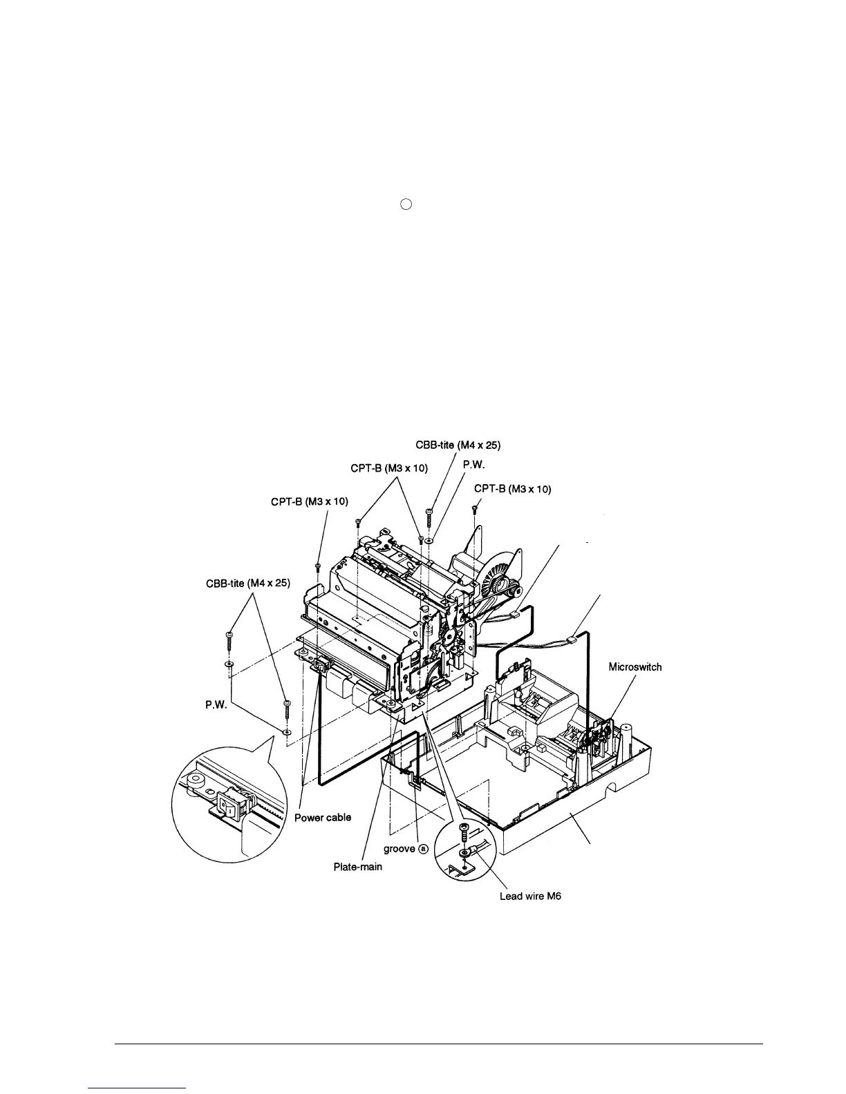
Main Assembly 5: Printer Mechanism Assembly Attachment on Case-Lower
Assembly
1. Gently place the printer mechanism assembly on the case-lower assembly.
2. Attach the power switch to groove .
3. Connect the connector assembly N.E. detector-J and -R from the printer mechanism
assembly to the microswitches.
4. Secure the printer mechanism assembly with the screws and washers. If the printer has a
MICR reader, secure lead wire M6 with a screw, as shown below.
✔
Checkpoints
Be sure to attach the power switch in the proper direction.
Make sure that each cable is firmly connected to its corresponding microswitch.
Be sure that the power cable is not caught between the plate-main and the case-lower
assembly.
a
Case-lower assembly
Connector assembly-N.E. detector R
Connector assembly-N.E. detector J
CONFIDENTIAL