Rev. A Disassembly, Assembly, and Adjustments 5-67
TM-U950/U950P Technical Manual
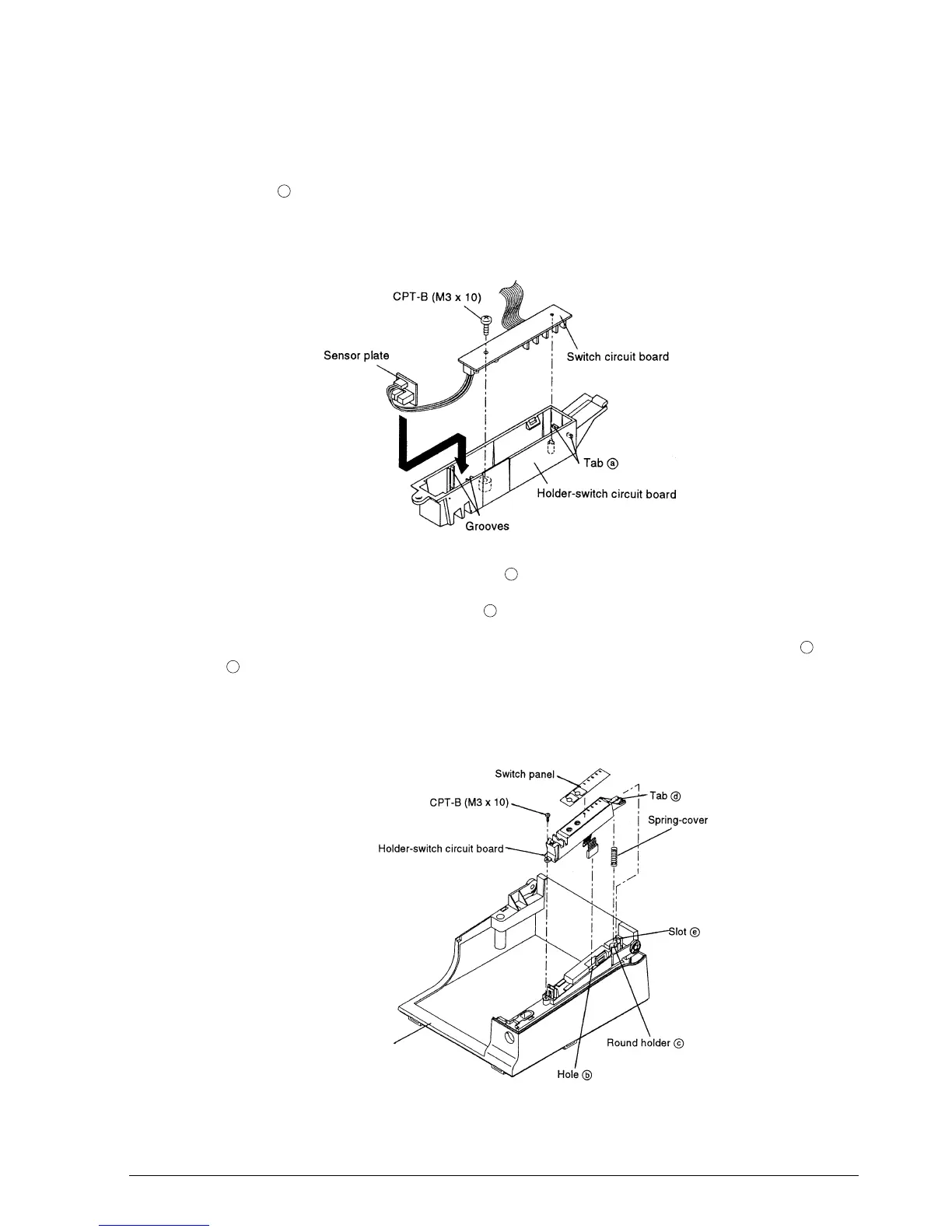
Sub-assembly B: Holder-Switch Circuit Board Assembly
1. Attach the switch circuit board to the holder-switch circuit board so that the board comes
under tabs , and secure the board with the screw.
2. Position the sensor plate by sliding it along the grooves of the holder-switch circuit board and
by passing the cables below the plate. Pay attention not to close the sensor with the wires.2
3. Pass the connector and cable through hole .
4. Place the spring-cover on round holder of the case-upper assembly.
5. Mount the holder-switch circuit board on the case-upper assembly by aligning tabs with
slot and pushing the holder down.
6. Paste the switch panel along the positioning adjustment line of the holder-switch circuit
board.
a
b
c
d
e
Case-upper assembly
CONFIDENTIAL