2-30 Mechanism Configuration and Operating Principles Rev. A
Main Board Operating Principle
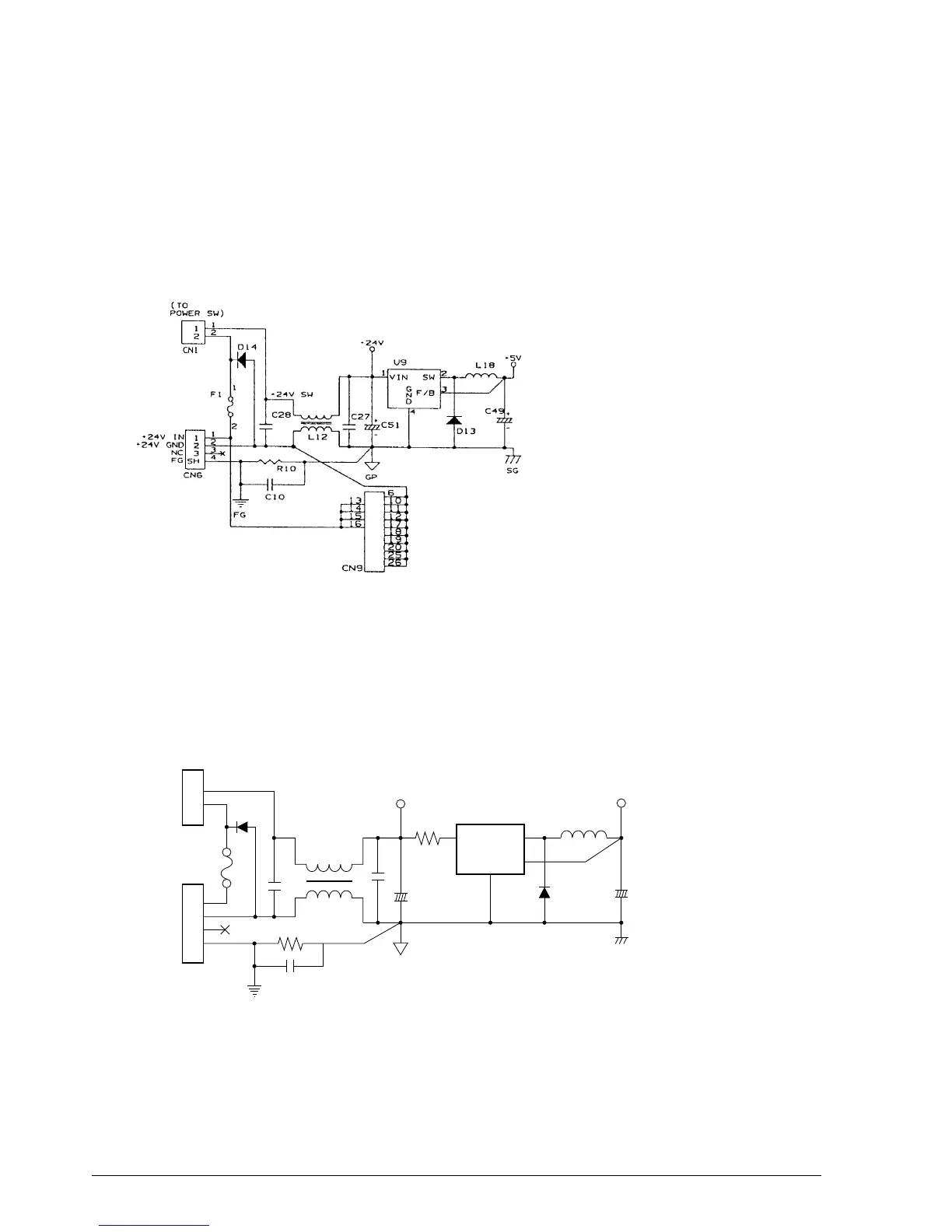
Power supply circuit for the TM-U950
The 24 V DC at CN6 (when IM-403/405 is not connected) or at CN9 (when IM-403/405 is
connected) is filtered and supplied to the +24 V line and the +5 V regulator circuit. The +5 V
regulator circuit uses the switching method to convert the +24 V input into a +5 V output. The
switching regulator IC (U9) switches the +24 V DC. The voltage is smoothed by L18, D13, and
C49, and is supplied as the +5 V output.
Power supply circuit for the TM-U950P
The 24 V DC at CN6 is filtered and supplied to the +24 V line and the +5 V regulator circuit. The
+5 V regulator circuit uses the switching method to convert the +24 V input into a +5 V output.
The switching regulator IC (U9) switches the +24 V DC. The voltage is smoothed by L18, D13,
and C49, and is supplied as the +5 V output.
Figure 2-45. Power Supply Circuit for the TM-U950
FG
1
2
2
1
CN1
C27
+
C51
_
+
C49
_
CN6
U9
L18
D13
C28
D14
F1
R10
C10
1
2
3
4
1
2
3
SH
L12
12
3
4
R224
+5V
SG
+24V
GP
FG
1
2
( TO
POWER SW )
IN
GND
NC
+24V
+24V
+24V
G
N
D
VIN SW
F/B
Figure 2-45a. Power Supply Circuit for the TM-U950P
CONFIDENTIAL