Rev. A Mechanism Configuration and Operating Principles 2-31
TM-U950/U950P Technical Manual
Control circuitry
CPU (M37702)
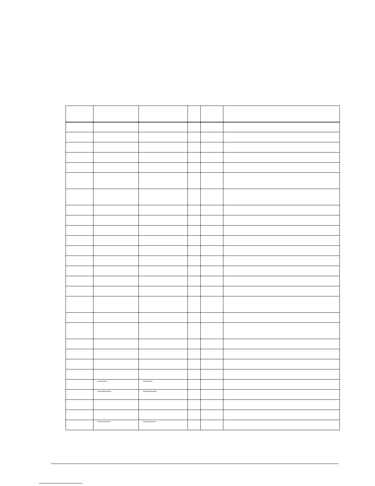
The CPU controls all printer operations according to a control program in ROM. The CPU pin
assignments are shown in Table 2-1.
Table 2-1. CPU Pin Assignments
Pin
number
CPU function Signal designation I/O Level Description
1 ANO V_DTC I Analog Detect 24 V voltage
2 P67 PFR2 O TTL Receipt paper feed motor Phase C,D
3 P66 PFR1 O TTL Receipt paper feed motor Phase A, B
4 P65 PFJ2 O TTL Journal paper feed motor Phase C, D
5 P64 PFJ1 O TTL Journal paper feed motor Phase A, B
6 P63 DSR I TTL
DSR signal input from serial interface on the
host
7P62
CSTRB(CSTB for the
TM-U950P)
I TTL Not used (receive interrupt for the TM-U950P)
8 P61 PFR_HL I/O TTL Receipt paper feed motor hold H = hold
9 P60 PFJ_HL I/O TTL Journal paper feed motor hold H = hold
10 P57 DKD_2 O TTL Drawer kick-out drive signal 1 L = drive
11 P56 DKD_1 O TTL Drawer kick-out drive signal 2 L = drive
12 P55 AC_2 O TTL Auto-cutter motor drive signal 2
13 P54 AC_1 O TTL Auto-cutter motor drive signal 1
14 P53 SHB O TTL Slip paper holder solenoid drive signal L=drive
15 P52 ER_LED O TTL Error LED drive signal L = ON
16 P51 SL_LED O TTL Slip paper LED drive signal L = ON
17 P50 CSOK O TTL
Slip paper eject detector LED drive signal L =
ON
18 P47 STB O TTL Stamp solenoid drive signal L = ON
19 P46 CR_NM O TTL
Carriage motor control signal H = normal
rotation
20 P45 CR_HL O TTL Carriage motor control signal H = hold
21 P44 CR_2 O TTL Carriage motor control signal Phase C, D
22 P43 CR_1 O TTL Carriage motor control signal Phase A, B
23 (0) FAI O TTL Receive interrupt
24 (RDY
) (RDY) I TTL Fixed to H (pulled up to +5V)
25 (HOLD
)(HOLD) I TTL Fixed to H (pulled up to +5 V)
26 BYTE BYTE I TTL Fixed to H (pulled up to +5V)
27 (CNV
ss
)(CNV
ss
) I TTL Fixed to H (connected to +5 V)
28 (RESET
)(RESET) I TTL Reset signal input L = reset
CONFIDENTIAL