5-72 Disassembly, Assembly, and Adjustments Rev. A
Main Assembly 3: Printer Mechanism Assembly Attachment on Plate-Main
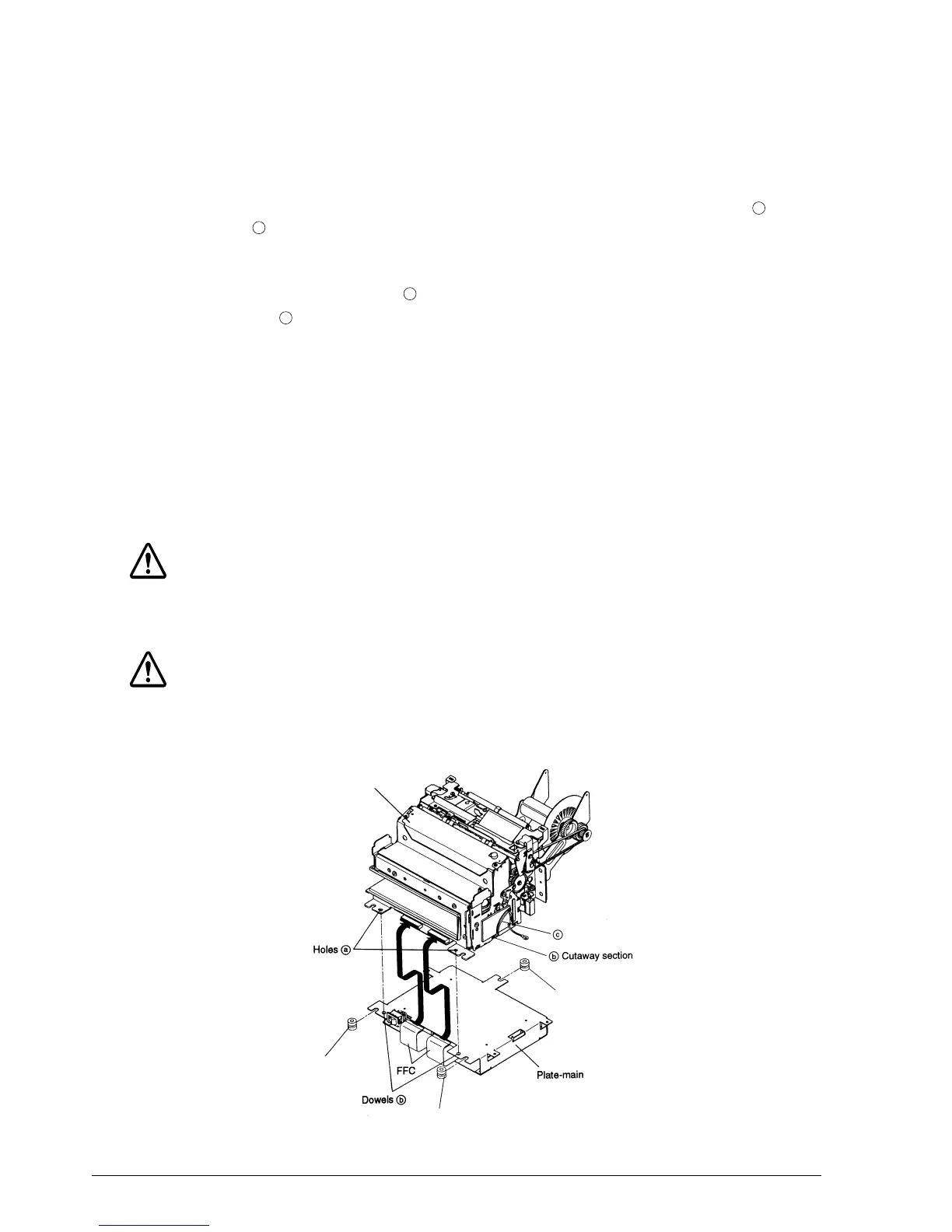
1. Turn over the assembled plate-main.
2. Gently place the printer mechanism assembly on the plate-main by aligning holes
with dowels .
✔
Checkpoints
Position the three cables (marked in the illustration) so that they are aligned with the
cutaway section . If the cables are not positioned properly, short circuits may occur, and
the circuit board may be damaged.
3. Insert the two FFCs on the plate-main into the connectors on the printer mechanism
assembly.
4. Mount the spacer-vibration assemblies in the U-shaped grooves of the plate-main.
✔
Checkpoints
Be sure to mount the spacer-vibration assemblies so that the rubber side faces up.
Make sure that the FFCs are firmly locked into their connectors.
CAUTION:
When you disconnect the FFCs from its connectors, be sure to pull it out straight. Otherwise you
may damage connector pins.
CAUTION:
When unplugging the FFC from the mechanical assembly, pull it straight, and not at an angle.
Pulling it at an angle can damage the pins of the connector.
a
b
c
d
Printer mechanism assembly
Spacer-vibration assembly
Spacer-vibration assembly
Spacer-vibration assembly
CONFIDENTIAL