2-4 Mechanism Configuration and Operating Principles Rev. A
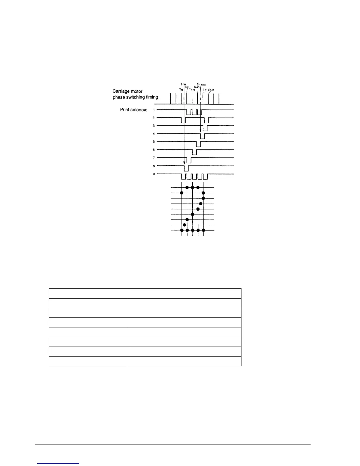
For example, to form the character “2”, print solenoids 2 and 9 are first powered in sync with the
carriage motor phase switching signal. Next, a half-dot timing delay TnH is introduced, and
print solenoid 8 is powered. By continuing in this way, the character “2” is formed.
Sensor Assemblies:
The sensor functions of the TM-U950 and TM-U950P are as follows:
(*) The near-end sensor is mounted on the case at the paper feed section
Sensor Assembly Function
Home position sensor assembly Initial TM-U950/TM-U950P setting
Carriage sensor assembly Detection of head carriage operation problems
Auto-cutter sensor assembly Auto-cutter stroke detection
Slip paper insert sensor assembly Slip paper presence detection
Slip paper eject sensor assembly “
Paper sensor assembly Roll paper presence detection
Near-end sensor assembly (*) “
Figure 2-4. Print Timing Chart
CONFIDENTIAL