Rev. A Mechanism Configuration and Operating Principles 2-25
TM-U950/U950P Technical Manual
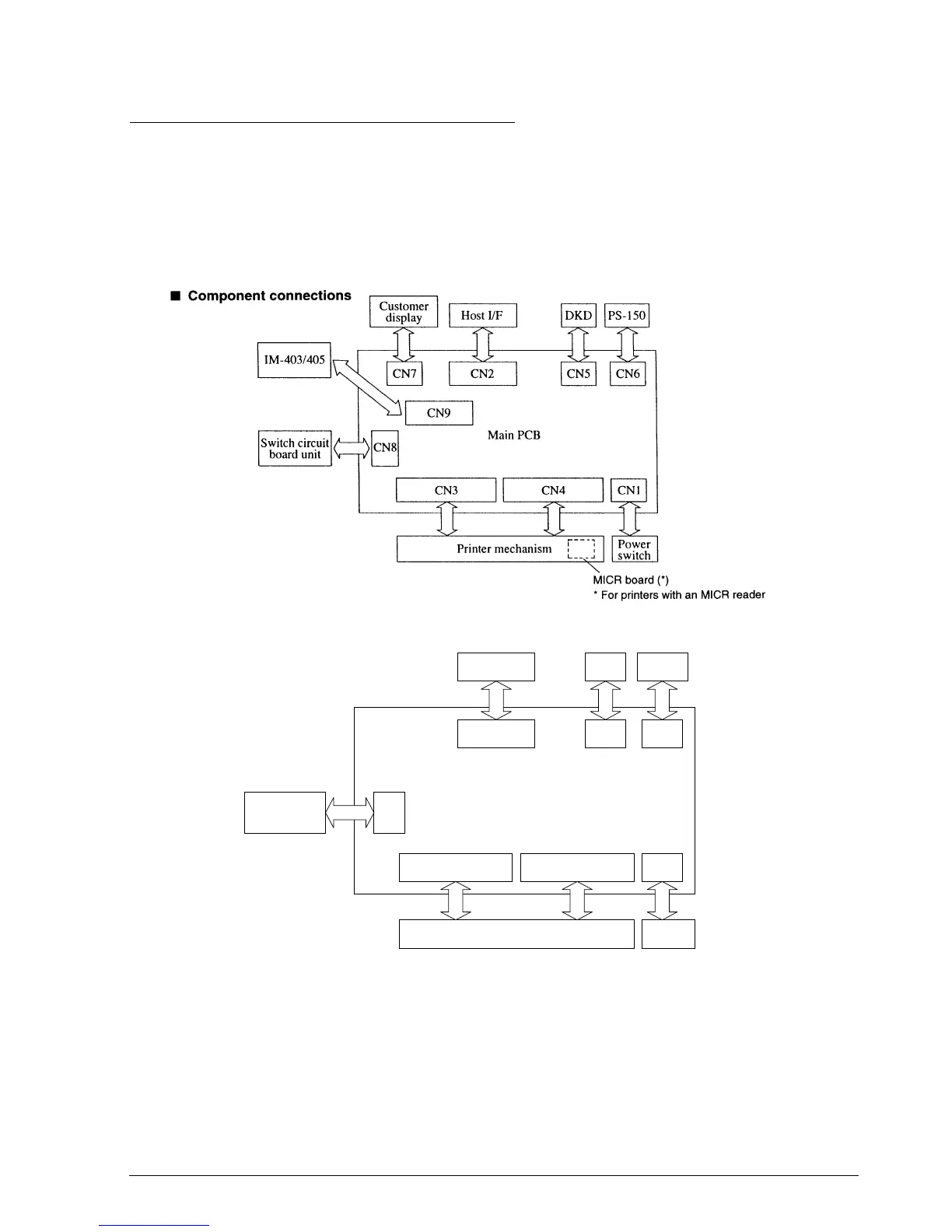
Electrical Circuitry Operating Principles
Hardware Configuration
The electrical circuitry of the TM-U950 is divided into the main PCB and the switch PCB unit.
These connections are shown in Figs. 2-40, 2-41, and 2-42.
❏ MICR board (for printers with an MICR reader) (not available for the TM-U950P)
The main board, switch board, and MICR board (on printers with an MICR reader) contain the
following electrical circuits.
Figure 2-40. TM-U950 Component Connection Chart
Figure 2-40a. TM-U950P Component Connection Chart
CN3 CN4 CN1
Host I/F DKD PS-150
CNIF1 CN5 CN6
Printer mechanism
Power
switch
CN8
Switch circuit
board unit
Circuit Board Unit
CONFIDENTIAL