Rev. A Disassembly, Assembly, and Adjustments 5-71
TM-U950/U950P Technical Manual
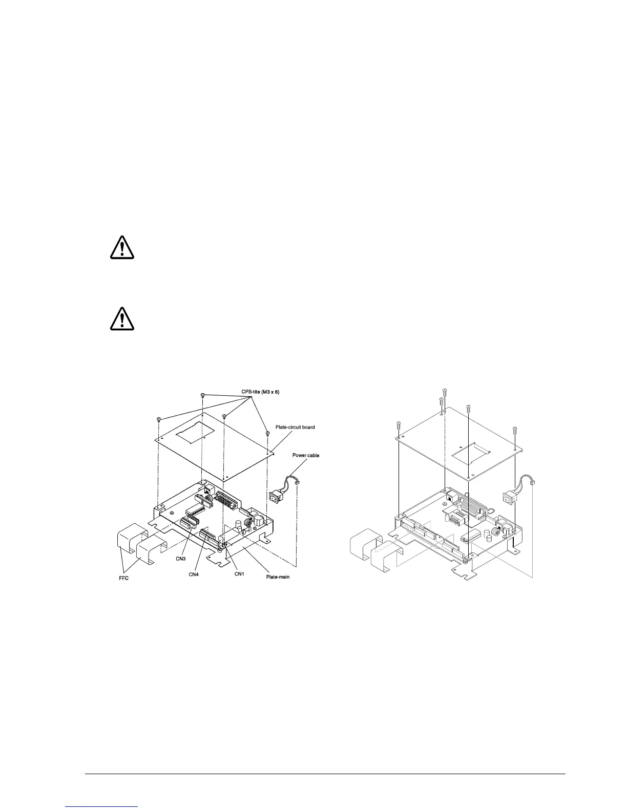
Main Assembly 2: FFC, Power Cable, and Plate-Circuit Board Attachment
1. Insert two FFCs into connectors CN3 and CN4, and then bend the FFCs as in the illustration.
2. Insert the power cable into connector CN1.
3. Mount the plate-circuit board by aligning its indentations with the tabs on the plate-main.
✔
Checkpoint
Make sure that the power cable and FFCs are firmly locked into their connectors.
Make sure not to mistake the direction of the FFCs.
CAUTION:
When you disconnect the FFCs from their connectors, be sure to pull them out straight. Otherwise
you may damage the connector pins.
CAUTION:
When unplugging the FFC from the mechanical assembly, pull it straight, and not at an angle.
Pulling it at an angle can damage the pins of the connector.
TM-U950 TM-U950P
CONFIDENTIAL