Rev. A Mechanism Configuration and Operating Principles 2-29
TM-U950/U950P Technical Manual
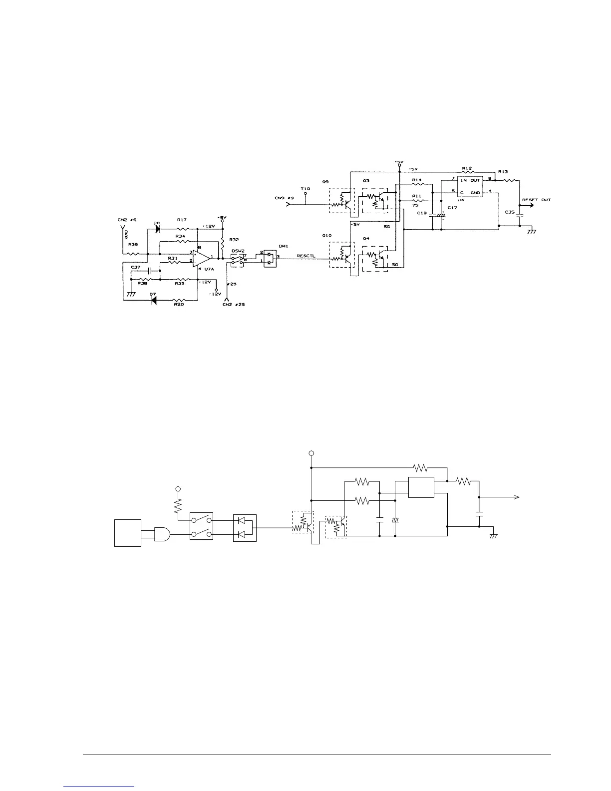
Reset circuit for the TM-U950
The reset IC (M51953BFP) monitors the +5 V voltage. When the voltage becomes more than 4.5
V, the IC releases the reset condition for the CPU and other circuits, thus enabling normal
printer operation. When a reset signal from the host is sent from the host interface (DSR, #25)
more than 1 ms, the output of the reset IC becomes low and the CPU and other circuits are reset.
Reset circuit for the TM-U950P
The reset IC (M51953BFP) monitors the +5 V voltage. When the voltage becomes more than 4.5
V, the IC releases the reset condition for the CPU and other circuits, thus enabling normal
printer operation. When the interface reset signal (nInit, #31) is added to the reset circuit more
than 50 µs when the host interface is in forward direction transmission (I/F signal 1284 ACT, #36
is low), the reset IC becomes low and the CPU and other circuits are reset.
Figure 2-44. Reset Circuit for the TM-U950
Figure 2-44a. Reset Circuit for the TM-U950P
Q10
8
7
1
2
DSW2
DM1
3
Q4
RESCTL
SG
R14
R11
+
C17
_
C19
R12
IN OUT
5
7
C GND
4
6
R13
C35
RESET OUT
+5V
+5V
nInit
1284ACT
CN1
CONFIDENTIAL