5-66 Disassembly, Assembly, and Adjustments Rev. A
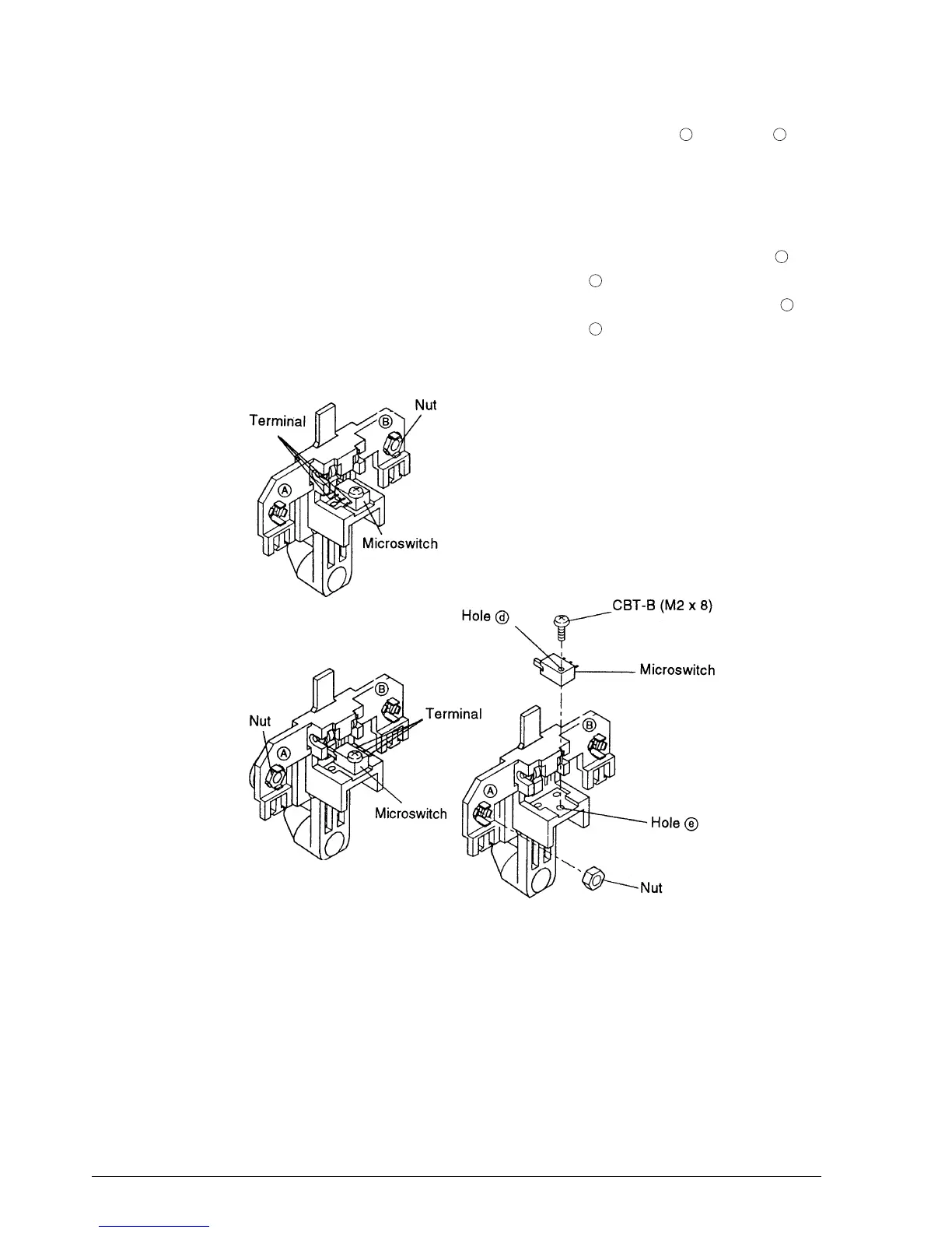
3. Attach the microswitch to the holder-N.E. detection by positioning hole over hole ;
then secure the switch with the screw.
4. Place a nut on each holder-N.E. detector.
✔
Checkpoints
For N.E. detector-J assembly, make sure to attach the nut on the holder marked with ,
and attach the microswitch so that the terminal faces mark .
For N.E. detector-R assembly, make sure to attach the nut on the holder marked with ,
and attach the microswitch so that the terminal faces mark .
Verify that the nuts are installed correctly with their curved surfaces facing outward.
d
e
b
a
a
b
N.E. detector-J assembly
N.E. detector-R assembly
CONFIDENTIAL