Rev. A Disassembly, Assembly, and Adjustments 5-15
TM-U950/U950P Technical Manual
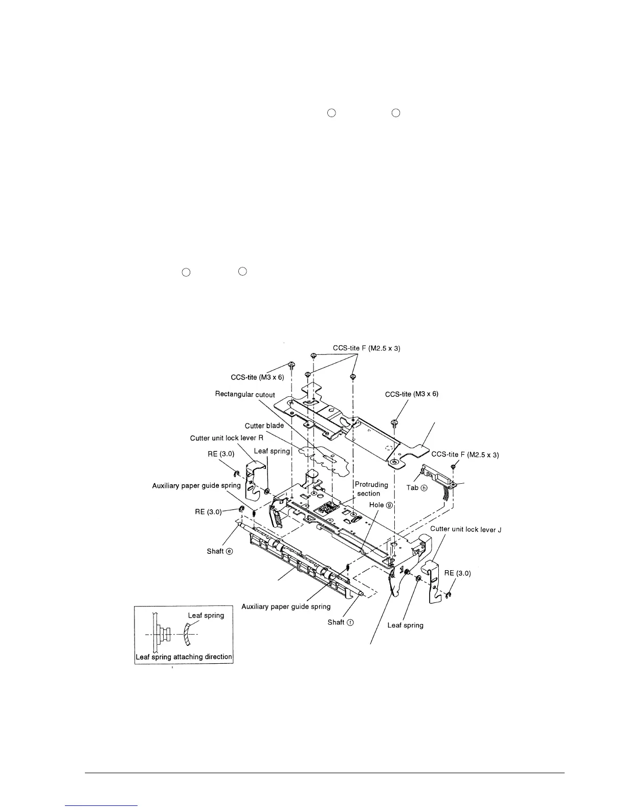
Sub-assembly H
8. Pass the roller-paper hold assembly shaft then shaft through holes and fasten the RE.
9. Attach the auxiliary paper guide springs.
10. Make sure that there is only one leaf of the cutter blade, and align the rectangular cutout on
the cutter blade with the protruding section on the cutter slide assembly.
11. Fasten the cover-cutter blade receiving assembly to the frame-cutter blade receiving
assembly with the screws.
12. Pass the leaf springs onto the shaft, mount cutter unit lock levers R and J, and fasten them
with REs.
13. Align hole with tab on the detector-slip ejection assembly and tighten the screws.
✔
Checkpoint
Make sure that the roller-paper hold assembly and the leaf springs are mounted in the
correct orientation.
e
f
g
h
Cover-cutter blade receiving assembly
Roller-paper hold assembly
Frame-cutter blade receiving assembly
Detector-slip
ejection assembly
CONFIDENTIAL
 Loading...


