5-64 Disassembly, Assembly, and Adjustments Rev. A
Main Assembly 2-3:
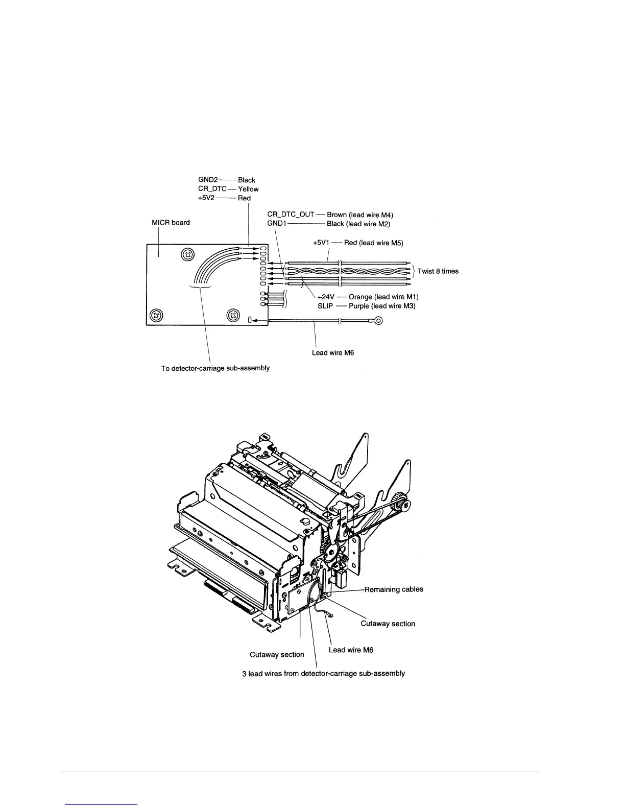
5. Twist lead wires M2 and M4 eight times, and solder them to the MICR board.
6. Solder lead wires M1, M3, M5, and M6 to the MICR board.
7. Solder the three lead wires from the detector-carriage sub-assembly to the MICR board.
8. Position the lead wires as shown in the illustration below.
CONFIDENTIAL
 Loading...


