2-50 Mechanism Configuration and Operating Principles Rev. A
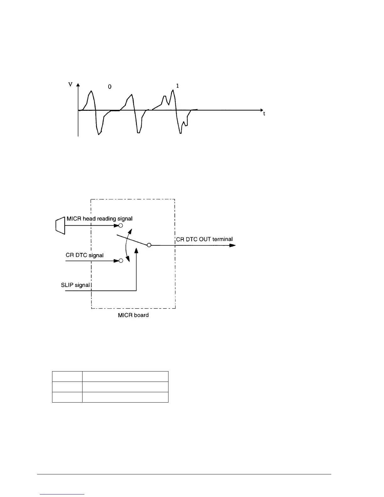
The voltage waveform output from the magnetic reading head produces a different pattern for
each individual character, and characters are recognized by their patterns.
Overview of MICR board operation
The following drawing shows a simplified diagram of the functions of the MICR board.
The MICR head reading signal and CR DTC signal are output to the CR DTC OUT terminal.
Switching of these two signals is controlled by the SLIP signal as shown below.
(Note: Only the logic for High and Low is shown. These are different from the TTL levels.)
SLIP signal
CR DTC OUT terminal
High
CR DTC signal output
Low
MICR head reading signal output
Figure 2-65. Voltage Waveform Output From the Magnetic Reading Head
Figure 2-66. General Operation of the MICR Board
CONFIDENTIAL