Appendix A Assembly Instructions
A-4 ER1 User Guide
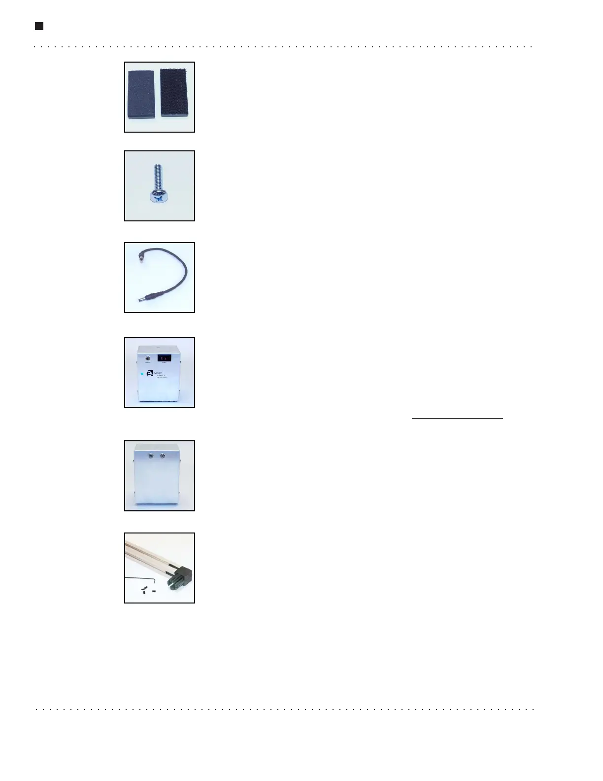
Mounting Plates
Mounting plates come in two varieties: foam (left) and mushroom
headed fastner tape (right). Mushroom headed fastner tape is similar to
Velc r o
®
, but is designed for heavy-duty, industrial uses. There are seven
mounting plates in your kit.
Philips Screw
The Philips screws are used to connect a variety of components to each
other. There are three Philips screws in your kit.
Power Cord
The power cord connects the power module to the Robot Control
Module. There is 1 power cord in your kit.
Power Module (Battery Pack)
The power module is connected by the power cord to the Robot Control
Module (RCM). It provides power to the robot's wheels and any robot
peripherals. Note the on/off switch on the top. This is how you will turn
off the ER1’s motors. There is one power module in your kit. To order an
additional power module, go to our website at www.evolution.com
.
This is the back view of the Power Module. The cable from the RCM
should be plugged into Input 1. Input 2 is for later accessories and is not
used by the robot at this time.
Set Screws
Set screws should be added to all of the plastic connectors once they are
in place. If you look carefully, all of the connectors have small holes in
the sides. Once a connector has been placed in the XBeam, screw the set
screw into the hole until it securely touches the beam. The setscrew,
when installed correctly, should be below the surface of the connector,
not flush with the surface. Do not overtighten. Until you do this, you will notice that the
connection will be very loose. The smallest Allen wrench is used to screw in the set
screws. There are 100 set screws included in your kit. This is more than you will need, so
don’t worry about counting them.