Appendix A Assembly Instructions
A-14 ER1 User Guide
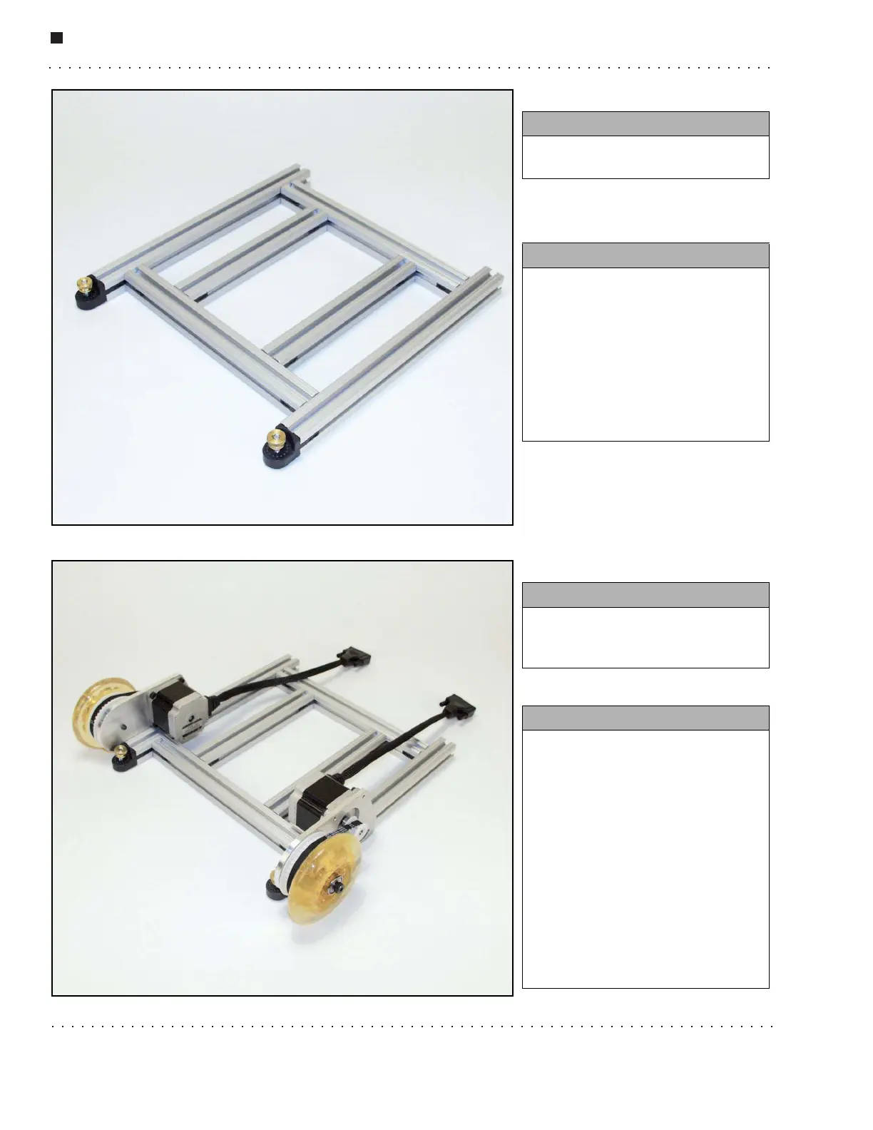
Step 6.
Step 7.
You need:
• The 12'' beams from the previous
step.
Instructions:
• Attach the 12'' beams to the 10''
beams by sliding them onto the
U-clips on the ends of the 10''
beams.
• Make sure there is 1'' clearance
on the ends of the 12'' beams.
• Make sure the thumbnuts are
facing up as shown.
You need:
• 2 Wheel assemblies with 4 Allen
screws with 2 one-holed T-nuts
attached.
Instructions:
• Loosen the T-nuts on the screws.
• Slide the T-nuts down the track
of the 12'' XBeam to the bottom
making sure that the motors are
oriented as shown.
• Be sure to slide the wheel
assembly all the way down to the
hinge and tighten the screws.
Make sure that the motor
mounting plate is flush with the
beams.
• Repeat for opposite side.