Appendix A Assembly Instructions
A-22 ER1 User Guide
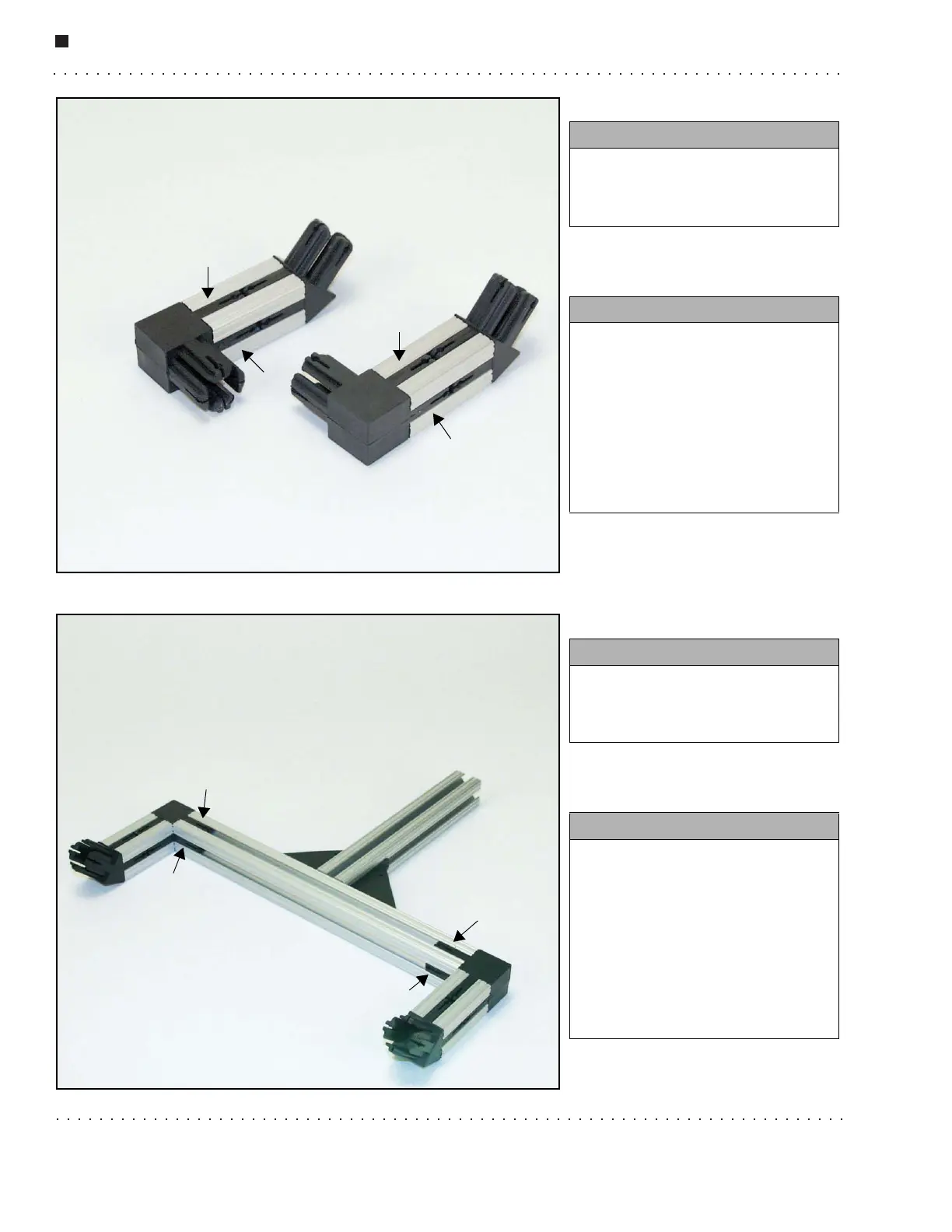
Step 22.
Step 23.
You need:
• 2 whole 90
o
connectors
(4 halves)
•Set screws
Instructions:
• Press the 90
o
connector halves
together
• Attach them to the end of the 2''
pieces as shown.
• Add the set screws to all four
sides of the 90
o
connectors (see
arrows - not all set screws
shown).
You need:
• Subassemblies from previous
steps
•Set screws
Instructions:
• Connect the subassemblies by
attaching the 2'' XBeams either
end of to the 10'' XBeam using
the 90
o
connectors.
• Add set screws to all four sides
of the 90
o
connectors where they
attach to the 10'' beam (see
arrows - not all set screws
shown).