Chapter 11 Port Explanation
107
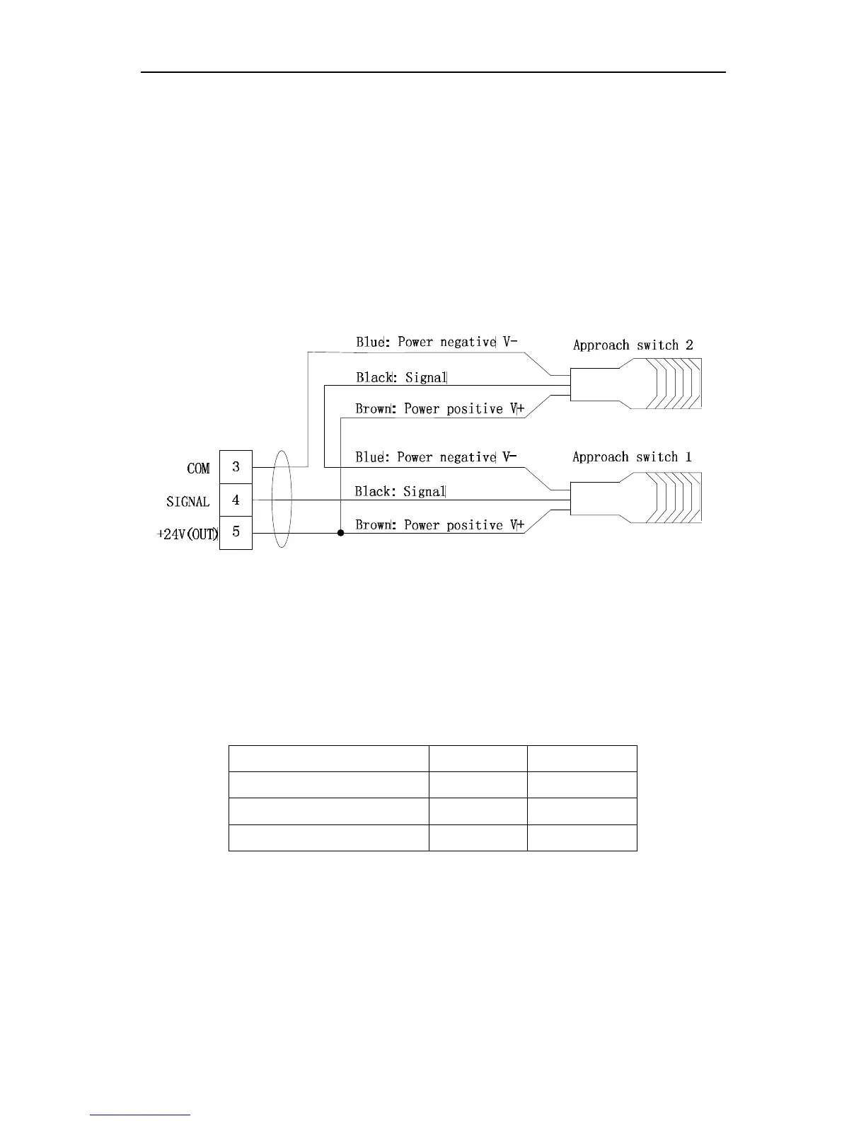
11.4.6 Wiring Diagram of double approach switch
Two NPN-style approach switches are used for location, which can either be linked
with the parallel mode or be linked with series mode. To make the location more accurate
and stable, we recommend using series mode to link the two switches. The specific wiring
mode is shown as the figure 11.15. With this link-mode, any one action of approach switch
can emit the collision signal.
Fig.11.15 Wiring Diagram of double approach switch
11.5 Power Input Instruction
Power input: 24V-、24V+、PE。
Table 11.8 Power Interface Signal Definition
3 Cores Interface Pin Number Signal Name Comment
1
24V-
24V Power -
2
24V+
24V Power +
3
PE
Ground