Chapter 3 Cutting Function
26
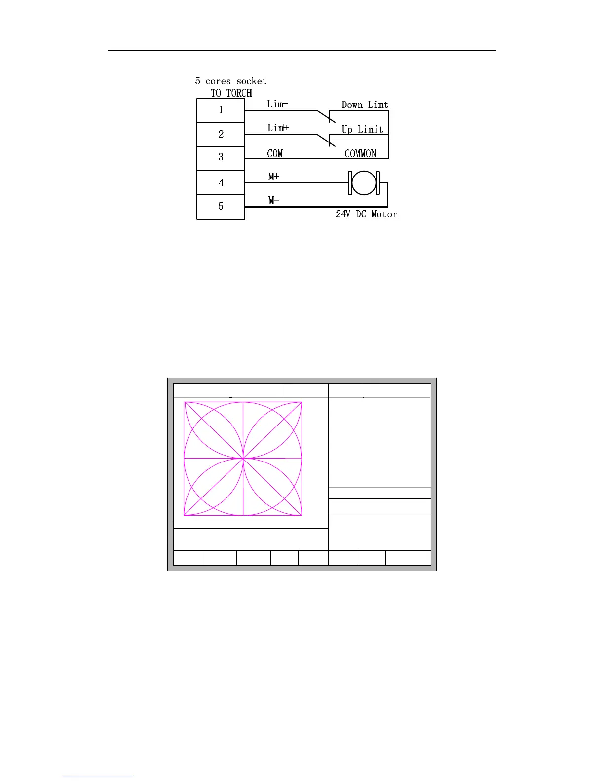
Fig.3.13 L
ifting body monitor and limit switch wiring
Interpret: specific system wiring interpretation with arc THC module, please
reference to the section of 11.4.4.
3.12.2 Arc Setting and Actual Arc Displaying
In the main interface or auto interface, display the arc setting and actual arc. Auto
interface is shown as the figure 3.14.
F1 Backward F2 Forward
F3
BacktoRefer
F4
SpeedDown
F5 SpeedUp
F6 ArcDec
F7 ArcAcc F8 JumpToPierce
FLSK F2200T
Version 3.3.73.1
Speed:
00000
File:
SHAPE_43.TXT
Status:
Stop
Current Line/Hole:
00000/00000
+X:500.00 -X:0.00 +Y:500.00 -Y:0.00
1:(TEST PATTERN)
2:G92
X:+000000.0
Y:+000000.0
●Positon Check s
●Arc Delay s
●Arc Check s
●Arc Striking Punch s
●TorchUp s
●TorchDn s
●Close THC
●Arc Feedback
●Location success
Manual 【F】 StepMov
StepDis【G】 5.00 Plasma Cu 【M】
CutSpeed 【X】3000.00 Kerf【N】0.00
ManualSpd 【Y】3000.00 Angle 0.00
Setting Arc: 120.0 Actual Arc: 0.0
[0] Auto Turn High
Fig.3.14 Auto interface with arc THC setting
3.12.3 Location Check
Locate with F2100T system: several settings needed to be done.