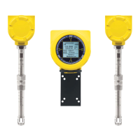
ST100A Series Flow Meter 06EN003480 Rev. A
Fluid Components International LLC vii
List of Tables
Table 1 – Compression Fitting Material .................................................................................................................................................... 8
Table 2 – Interconnecting Cable Minimum Conductor Size .................................................................................................................... 21
Table 3 – Modbus Select Jumpers ......................................................................................................................................................... 30
Table 4 – Modbus Line Configuration Jumpers ...................................................................................................................................... 30
Table 5 – FOUNDATION Fieldbus/PROFIBUS Select Jumpers ................................................................................................................. 31
Table 6 – Flow Parameters, HMI ............................................................................................................................................................ 38
Table 7 – Log File Filename Format LGabcdxx.csv ............................................................................................................................... 44
Table 8 – Log File Entry Example ........................................................................................................................................................... 44
Table 9 – Fatal Faults that Trigger NAMUR ............................................................................................................................................ 49
Table 10 – ST100A Series HART Process Variables ............................................................................................................................. 54
Table 11 – ST80/ST80L HART Field Device Registration Information ................................................................................................... 55
Table 12 – HART Universal Commands ................................................................................................................................................. 59
Table 13 – HART Common Practice Commands ................................................................................................................................... 66
Table 14 – ST100A Series HART Device Specific Command Groupings .............................................................................................. 68
Table 15 – HART Device Specific Commands ....................................................................................................................................... 68
Table 16 – Command Status Bytes, Bit Assignments ............................................................................................................................ 74
Table 17 – Command-Specific Response Codes ................................................................................................................................... 74
Table 18 – Command 48, Additional Device Status Bytes Bit Assignments ........................................................................................... 75
Table 19 – HART Engineering Units Codes ........................................................................................................................................... 76
Table 20 – ST100A Series Modbus Function Codes .............................................................................................................................. 78
Table 21 – ST100A Series Modbus Process Data ................................................................................................................................. 79
Table 22 – Modbus Service Data – Service and Setup Functions .......................................................................................................... 80
Table 23 – ST100A Series Modbus Engineering Unit Codes ................................................................................................................. 82
Table 24 – ST100A Series Modbus Exception Codes ............................................................................................................................ 83
Table 25 – ST100A Series Modbus Variables and Registers Map ......................................................................................................... 83
Table 26 – Power Fuse Summary .......................................................................................................................................................... 90
Table 27 – Lithium Coin Cell Battery Summary ...................................................................................................................................... 91
Table 28 – Flow Element Resistance Measurements (In Ohms) Taken From Remote/Integral Electronics .......................................... 95
Table 29 – Flow Element Resistance (In Ohms) at the Local Enclosure ................................................................................................ 95
Table 30 – Nominal Heater Parameter Ranges ...................................................................................................................................... 96
Table 31 – System Status LED D3 States .............................................................................................................................................. 97
Table 32 – Instrument Power Supply Voltages ....................................................................................................................................... 98
Table 33 – Basic CORE Fault Register (CORE CY Command) ........................................................................................................... 102
Table 34 – Detailed CORE Fault Register (CORE 2V Command) ....................................................................................................... 103
Table 35 – FE Fault Register (FE DF Command) ................................................................................................................................. 104
Table 36 – ST100A Series Drawings in Appendix A ............................................................................................................................. 105

 Loading...