Technical data 103
Short-circuit withstand
strength (IEC 60439-1)
Maximum allowable prospective short-circuit current:
50 kA or 65 kA (only with F296 in the 600 V model).
When you use temporary grounding (connect two sets of grounding cables to
the connecting knobs of the AC and DC busbars and PE of the inverter): The
maximum permitted prospective short-circuit current decreases to 45 kA /
1 s. To maintain the 65 kA rating, the fault current duration must be limited to
0.5 s. If the connected grounding cables and clamps are not equivalent to the
prospective short-circuit rating of the inverter, the total rating will be lower.
Frequency 45 to 65 Hz withstand with nominal dimensioning (grid-compliance may
require disconnection at stricter values).
Imbalance The inverter does not cause imbalance.
Voltage dips Max. 0% Refer to the Firmware manual.
Fundamental power factor
(cos phi
1
)
1
Power factor (cos phi
1
)
adjustment range
0…1 capacitive or inductive
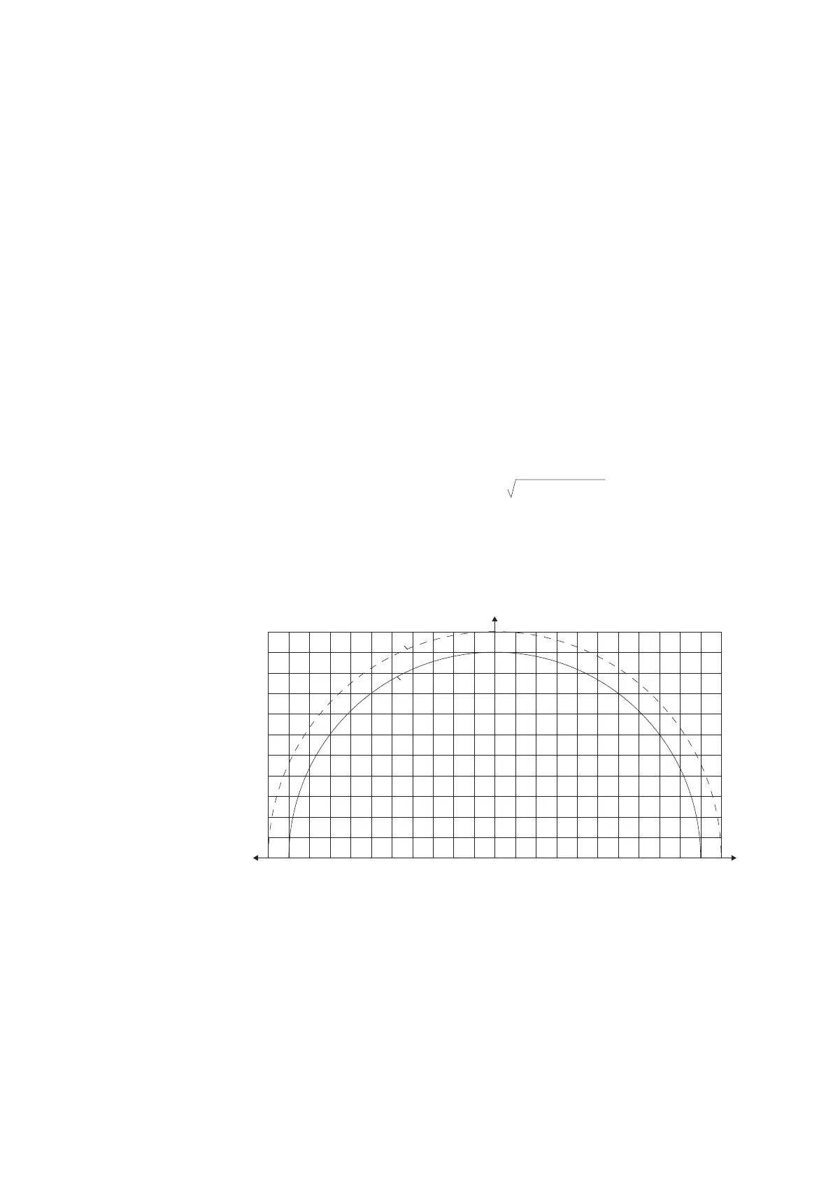
The graph illustrates inverter operation at the nominal AC voltage and
nominal ambient (50 °C) temperature. At 35 °C, up to 110% power available.
Refer to Ratings on page 94.
Current Refer to Ratings on page 94.
Maximum output fault
current
(Tested by making direct 3-
phase short circuit to
inverter output when
inverter is feeding nominal
current)
Output mains:
Peak: 5600 A
3 cycles (average): 370 A
Duration: 25 ms
3-phase customer aux:
Peak: 5000 A
3 cycles (average): 310 A
Duration: 1 ms
1-phase 115 V service outlet:
Peak: 400 A
3 cycles (average): 60 A
Duration: 3 ms
1-phase 230 V service outlet:
Peak: 470 A
3 cycles: (average) 100 A
Duration: 7 ms
P (%)
Q (%)
90
80
70
60
50
40
30
20
10
-10
-20
-30
-40
-50
-60
-70
-80
10 20 30 40 50 60 70 80 90 1000
100
-90
-100
Q (%) Available reactive power as a percentage of the
nominal apparent power
P (%) Available active power as a percentage of the
nominal apparent power
100
2
- P(%)
2
Q
max
(%) =
110
110
-110
35 °C
50 °C