Planning the electrical installation 67
Cabling
Warning! Obey the safety instructions on page 10. If you ignore the instructions,
physical injury or death, or damage to the equipment can occur.
As standard, the inverter is delivered with blind plates instead of cable lead-throughs.
Cable lead-throughs are option +H357. Refer to Cable lead-throughs on page 67.
The cable lead-throughs must be sealed
properly and one cable per lead-through must
be used so that the ingress protection class of
the inverter (IP56/66/Type 3R) (dust and
water proof) is maintained.
The PV array connections are made in the DC
input sections. The number of DC inputs
depends on the selected configuration.
The illustration shows an example of a
configuration with 8 DC inputs (8H382).
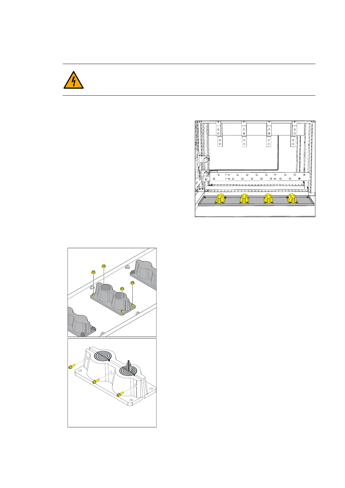
Cable lead-throughs
If they are delivered with the inverter, use the
cable lead-throughs. Make sure that you install the cable lead-throughs correctly so that
they maintain the IP class of the inverter (IP56/66) (dust and water proof).
To install the cables through the lead-through:
1.Remove the nuts that attach the lead-through to the
frame.
2.Route the cables into the DC input section.
3.Crimp the cable lugs and connect the conductors to
the terminals.
4.Open each lead-through with a hex head
screwdriver.
5.Remove the correct amount of gasket depending
on the cable diameter.
6.Install the cable in the cable gland and close the
lead-through. Make sure that the package is properly
tightened.
7.Attach the lead-through with the cable to the lead-
through plate.
DC connection
•Use compression cable lugs with 1 or 2 holes.
•The DC input terminals are tin-plated metal.
•Connect no more than two cables to each DC
connection terminal.
• Use only the recommended bolts, nuts and washers.
• Obey all indicated torques.