142 Control unit
ABB PM564
PM564
DI0
DI1
DI2
DI3
DI4
DI5
AI0
AI1
NO0
NO1
NO2
NO3
PWR
RUN
ERR
CPU PM564-RP-ETH 6DI 24VDC 6DO-R 240VAC 2A 2AI 1AO
1
6
7
8
9
10
11
12
13
14
15
16
3
4
5
2
C0..5
DI4
DI5
AI0
AI1
AOI
AOU
M
NO0
NO1
NO2
R0..2
DI1
DI2
DI3
DI0
18
19
20
NO4
NO5
R3..5
COM1
17 NO3
WARNING!
Use of
incorrect
battery may
cause fire or
explosion
NO4
NO5
AO
COM2
RUN
STOP
SD CARD COM2
INSERT
PUSH
MC
502
ETHERNET
L+ M FE L+ M
24VDC OUT24VDC IN
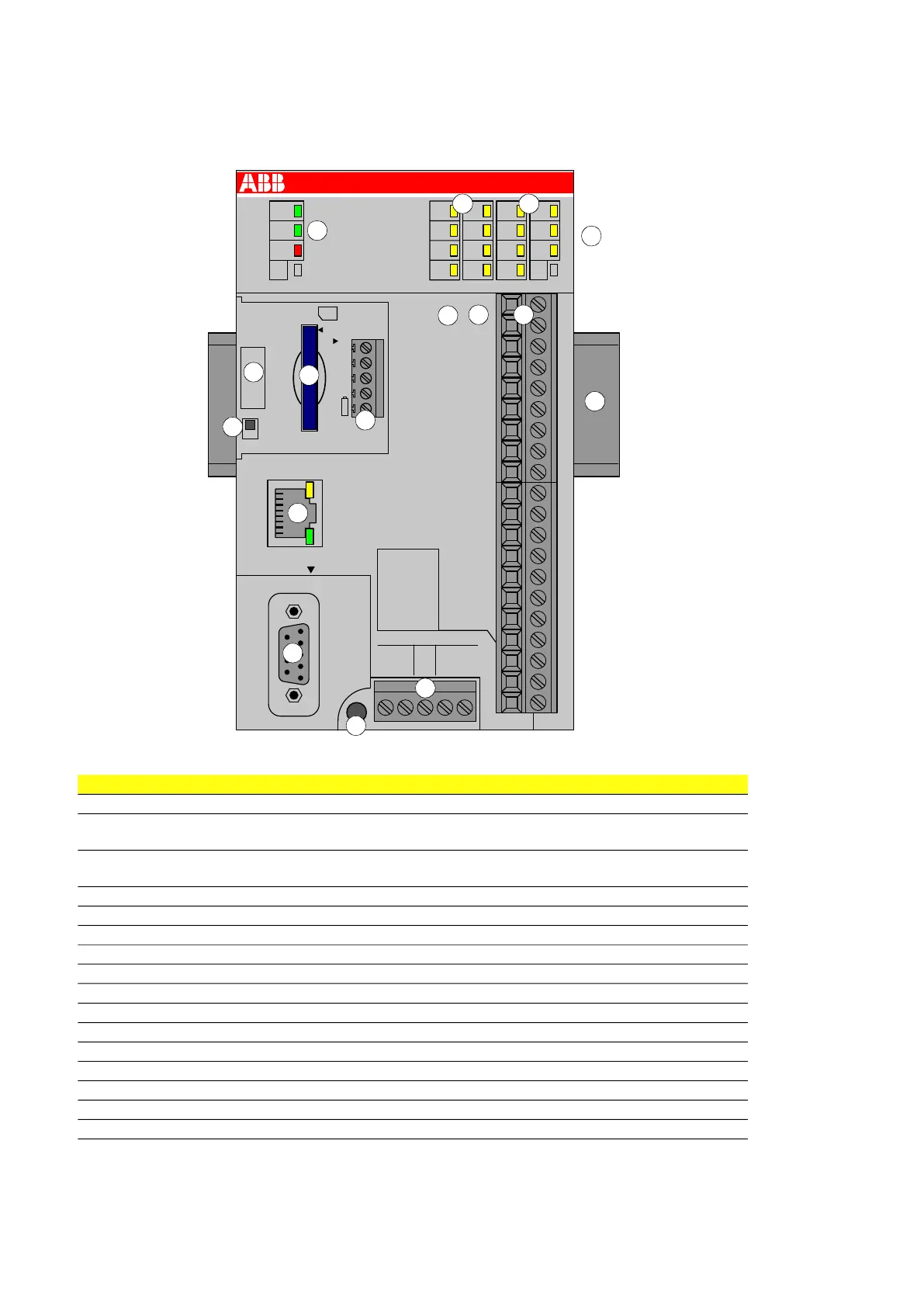
No. Description
1. 3 LEDs show the status of the CPU
2. 6 yellow LEDs show the state of the digital input signals
2 yellow LEDs show the state of the analog input signals
3. 6 yellow LEDs show the state of the digital output signals
1 yellow LED shows the state of the analog output signal
4. I/O bus for additional I/O modules
5. Terminal number
6. Allocation between terminal number and signal name
7. Terminals for the input and output signals (20-pin, not removable)
8. 5-pin removable connector for COM2 (optional)
9. Handle for opening the cover for the expansion modules
10. SD memory card slot (optional)
11. RUN/STOP switch
12. Ethernet interface
13. 9-pin SUB-D jack (COM1) for RS-485 connection
14. 2 holes for wall mounting with screws
15. 5-pin removable connector for power supply (24 V DC or 100-240 V AC depending on model)
16. DIN rail
1
2 3
4
5
6
7
8
9
10
11
12
13
14
15
16