66 Planning the electrical installation
I/O connection diagram
There are 7 digital inputs, 2 analog inputs and one digital/relay output available as
standard to, for example, connect transformer monitoring signals to the inverter so that
they can be read and monitored directly from inverter parameters. The connection point for
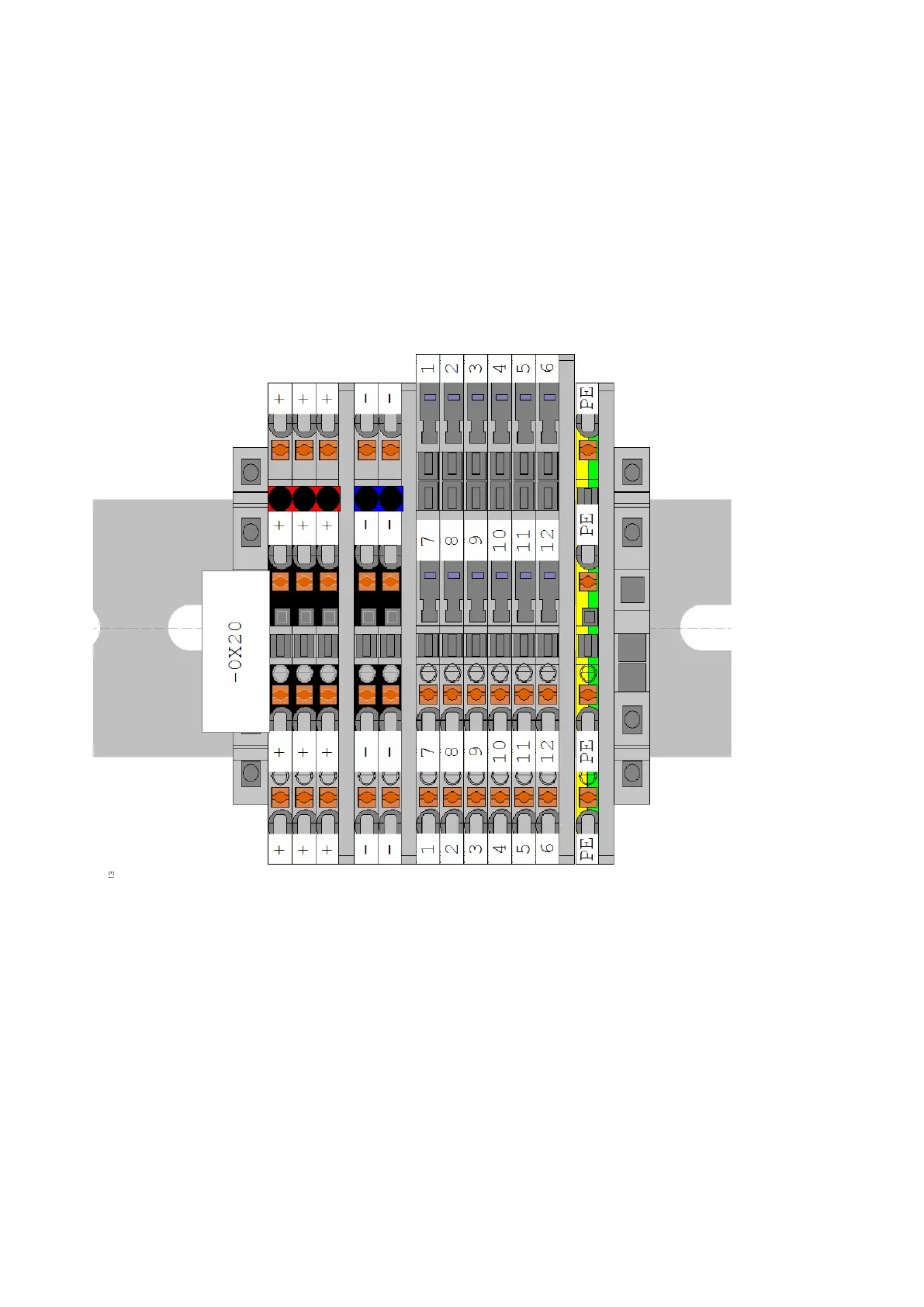
these is the X20 terminal. Refer to Auxiliary power and I/O connections on page 134.
You can configure the I/O signals with different fault names and reactions. For more
information, refer to the Firmware manual. You can load the I/O interface with a total of
500 mA.
X20 I/O module connections: