28 Operation principle and hardware description
Cooling system
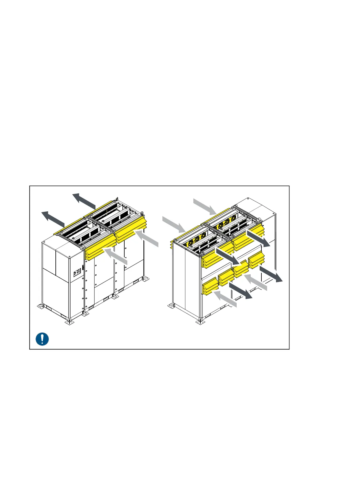
Heat exchangers based on advanced thermosiphon technology in the main cooling
channel cool the power semiconductors and the inverter indoor sections. The air inlet of
the main cooling channel is at the top front side of the inverter. The exhaust air flows from
the top rear of the inverter. Cooling fans in the inverter circulate the cooling air internally.
The cooling medium (R134a refrigerant) in the heat exchangers moves due to gravity and
phase transition. A pump or compressor is not needed. The cooling medium moves the
generated heat to the top of the cooling elements and to the external cooling air channel. A
fan creates the external cooling air flow. The external air channels are protected by water
separator louvres. Air filters are unnecessary.
The LCL filter of the inverter uses the same cooling principle. The LCL cooling system is
on the rear of the inverter. The direction of the cooling air flow in the LCL section depends
on the position of the fans. Refer to the project documentation.
The double layer walls of the cabinet insulate the inverter effectively from external heat.
Main cooling channel
LCL cooling
Note: The roof has been removed for illustrative purposes.