Planning the electrical installation 61
To operate as a protective conductor, the shield conductivity requirements according to
IEC 61439-1 are shown below when the protective conductor is made of the same metal
as the phase conductors:
According to NEC (National Electrical Code, applicable in the USA), the size of the
grounding conductor must not be less than defined in this table:
Busbar dimensioning
Dimension the busbars according to the maximum output current and the instructions of
the manufacturer regarding temperature coefficients and load profiles. For more
information, contact FIMER.
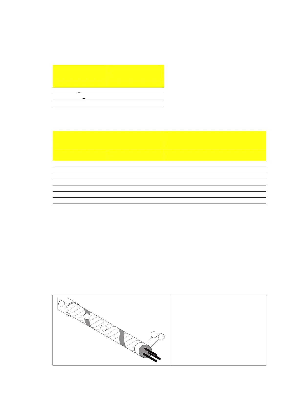
Sufficient shield conductivity to suppress emissions
To effectively suppress radiated and conducted radio-frequency emissions, the cable
shield conductivity must be at least 1/10 of the phase conductor conductivity. The
requirements are easily met with a copper or aluminum shield. The minimum requirement
of the cable shield is shown below. It consists of a concentric layer of copper wires with an
open helix of copper tape or copper wire. The better and tighter the shield, the lower the
emission level.
Cross-sectional area of
the phase conductors
Minimum cross-sectional
area of the corresponding
protective conductor
S (mm
2
) S
p
(mm
2
)
S <
16 S
16 < S <
35 16
35 < S S/2
Size of largest ungrounded service-entrance
conductor or equivalent area for parallel conductors
(AWG/kcmil)
Size of grounding electrode conductor
(AWG/kcmil)
Copper Aluminum or copper-clad
aluminum
Copper Aluminum or copper-clad
aluminum
2 or smaller 1/0 or smaller 8 6
1 or 1/0 2/0 or 3/0 6 4
2/0 or 3/0 4/0 or 250 4 2
Over 3/0 through 350 Over 250 through 500 2 1/0
Over 350 through 600 Over 500 through 900 1/0 3/0
Over 600 through 1100 Over 900 through 1750 2/0 4/0
Over 1100 Over 1750 3/0 250
1. Insulation jacket
2. Copper wire screen
3. Helix of copper tape or copper wire
4. Inner insulation
5. Cable core
1
3
2
4
5