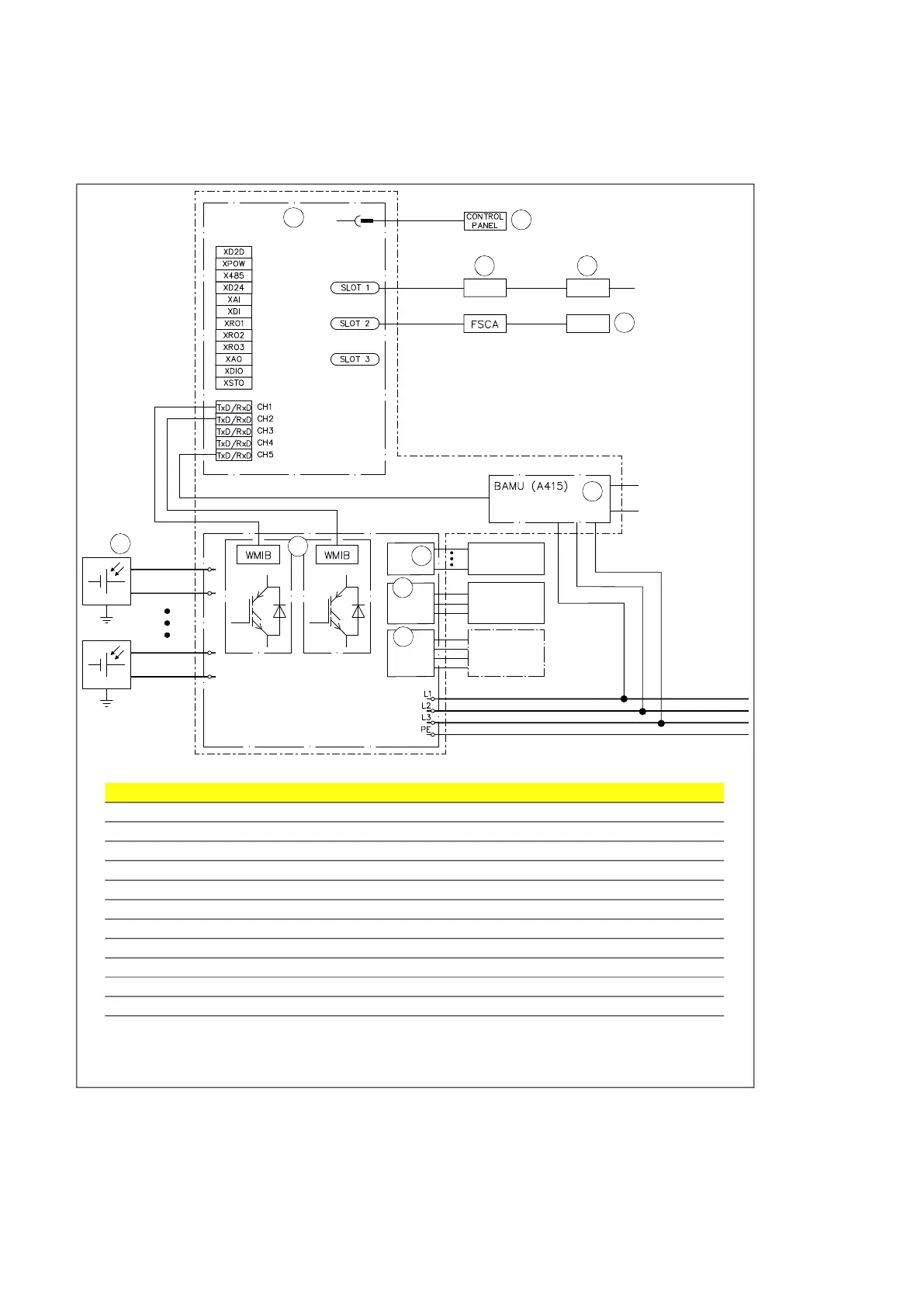
40 Operation principle and hardware description
Overview of power and control connections
ETHERNET
SWITCH
24 VDC
BCU-12
Customer I/O
X20
1~ Aux. power
X13
3~ Out for ext.
transformer
X12
L
N
PE
L1
L2
L3
PE
DC+
DC+
DC-
3 x U
FIELDBUS
ADAPTER
DC-
DC+
DC-
,2
No. Description
1. Control unit (BCU-12)
2. Control panel (ACS-AP-I)
3. Optional fieldbus adapter
4. Optional Ethernet switch
5. Internal I/O connected through a Modbus adapter (FSCA-01)
6. Solar array
7. Power modules
8. Customer I/O control connection
9. 1-phase auxiliary power output
10. 3-phase power output for external auxiliary transformer
11. BAMU-11. Auxiliary measuring unit: DC voltage, grid voltage measurement for BCU-12.
1
2
3
5
8
6
7
9
10
11
4