80 Electrical installation
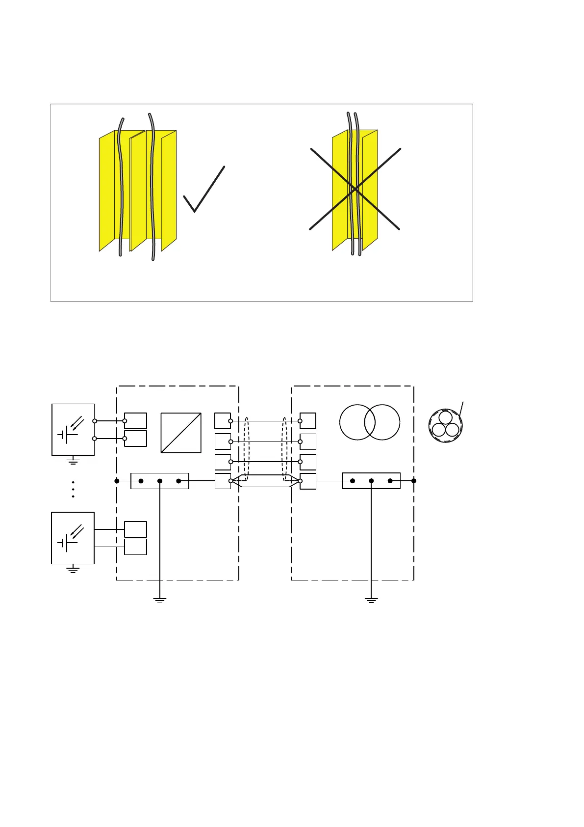
Separate control cable ducts
Connecting the power cables
Obey the instructions on cabling in Planning the electrical installation on page 57.
Connection diagram
1) Solar array junction box.
2) If you use a shielded cable, ground it at the cabinet entry. Ground the other end of the input cable shield
or PE conductor at the transformer.
3), 4) If you use a shielded cable and the conductivity of the shield is less than 50% of the conductivity of the
phase conductor, use a separate PE cable (3) or a cable with a grounding conductor (4).
5) In areas subject to NEC (National Electric Code of USA), the equipment grounding conductor in the bus
duct between the inverter main ground bar and the ground pad on the transformer tank should be as
per NEC Table 250.122.
Put 24 V and 230 V (120 V) control cables
in separate ducts inside the cabinet.
Not permitted, unless the 24 V cable is
insulated for 230 V (120 V) or insulated with
an insulation sleeving for 230 V (120 V).
24 V 230 V (120 V) 24 V 230 V (120 V)
=
~
L1
L2
L3
DC+
DC-
Ws^ϵϴϬ
DC+
DC-
L1
L2
L3
1)
2)
1)
3)
4)
PE
PE
P