140 Control unit
Layout and connections
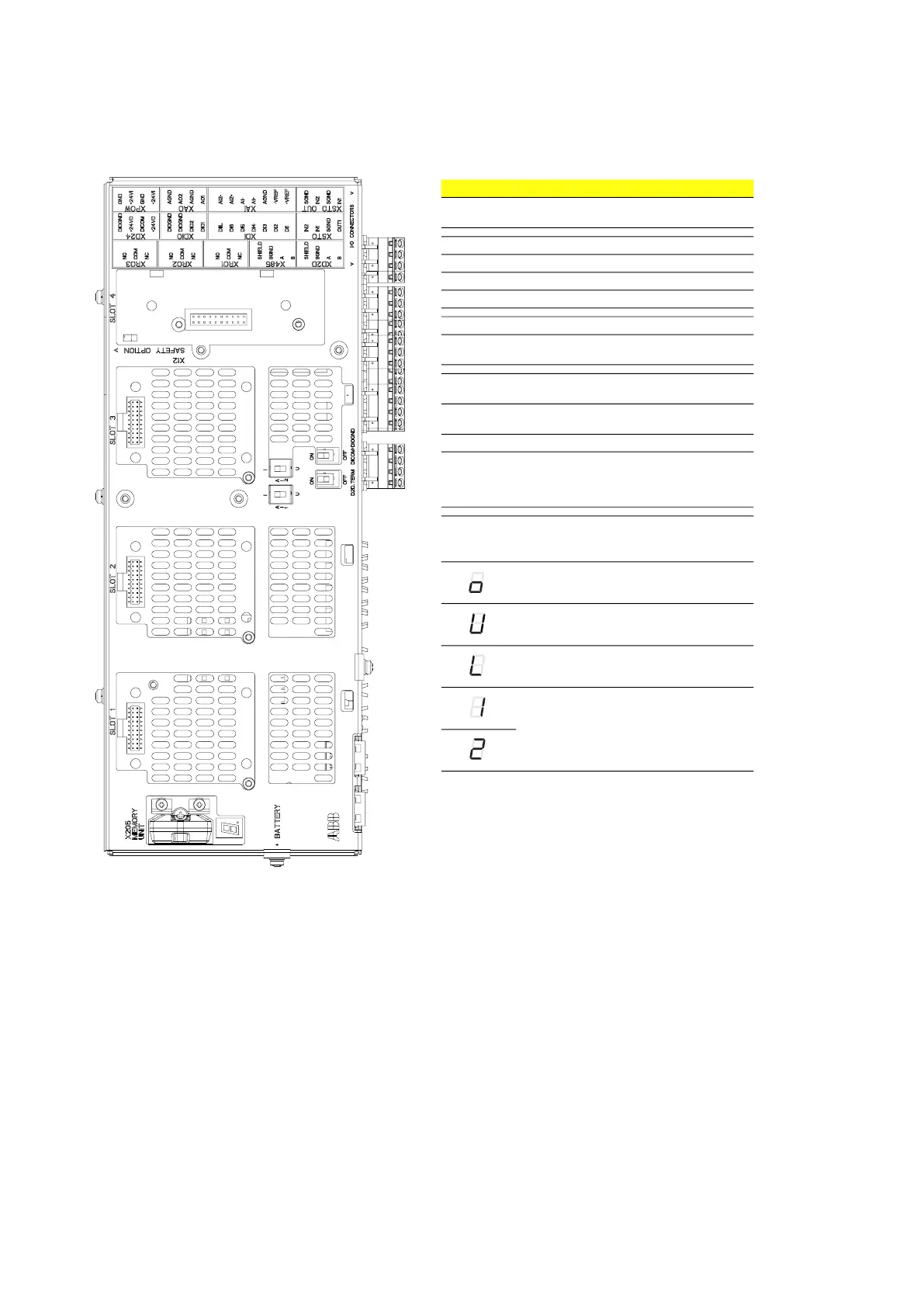
Item Description
I/O I/O terminals
(refer to I/O terminals on page 141)
SLOT 1 Fieldbus adapter module connection
SLOT 2 Used for internal connections
SLOT 3 Fieldbus adapter module connection
SLOT 4 Not in use
X205 Memory unit connection
BATTERY Not in use
(Holder for real-time clock battery)
AI1 Mode selector for analog input AI1
(I = current, U = voltage)
AI2 Mode selector for analog input AI2
(I = current, U = voltage)
D2D TERM Not in use
DICOM =
DIOGND
Ground selection. Determines whether
DICOM is separated from DIOGND (ie. the
common reference for the digital inputs
floats).
7-segment display
Multicharacter indications show as repeated sequences
of characters
(“U” shows briefly before “o”.)
Control program startup in progress.
(Flashing) Firmware cannot be started.
Memory unit missing or corrupted.
Firmware download from PC to control
unit in progress.
At power-up, the display may show short
indications of, e.g. “1”, “2”, “b” or “U”. This
is normal. If the display ends up showing
any other value than those described, it
indicates a hardware failure.