Planning the electrical installation 73
Protecting against ground faults in the DC input cable or
solar generator
The inverter has an automatic insulation resistance measurement device which monitors
the insulation. Because of the leakage currents of inverters and the characteristics of the
PV array, typically normal ground fault monitoring devices do not work correctly. Therefore,
non-PV-specific monitoring devices are not recommended. Do not add any other insulation
measuring device in the same galvanically connected circuit.
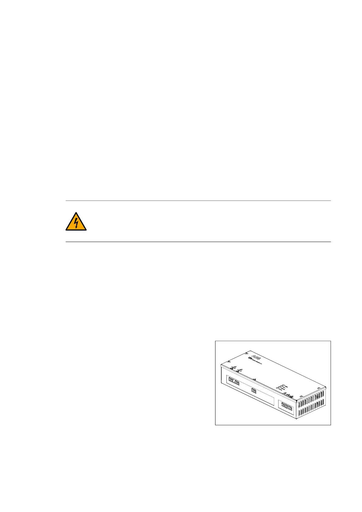
Insulation monitoring device MIRU-01
According to the IEC 62109-2 standard, insulation measurement is required before the
inverter is started. Insulation resistance is measured with the MIRU-01.
Safety information
The insulation monitoring device is constructed according to recognized technical safety
rules. Nevertheless, when the device is used, hazards can occur to life and limb of the
user or to third parties, or there may be adverse effects on the monitoring device or on
other valuable property.
WARNING! Use only one insulation monitoring device in each interconnected IT
system. Before you do an insulation resistance or voltage test, isolate the device
from the system for the test period. The ground fault monitoring function is not a
personnel safety or fire protection feature.
Operation
The measurement can be activated based on the usage of the grounding feature. MIRU-
01 measures insulation resistance between the DC busbars and protective earth (PE).
When the inverter operates, the insulation resistance of the AC busbars against the
protective earth is also measured indirectly. The monitoring device reacts to all ground
faults in IT systems which are galvanically connected to each other.
If the insulation resistance between the conductors and the ground falls below the set
response values, the inverter trips or generates an alarm depending on the parameter
settings. The measured insulation resistance value can be read from the inverter
parameters.
When insulation resistance measurement is
activated, a valid measurement is formed only after
some time has passed. An adjustable minimum
measurement time must elapse before the
measurement is ready. When the measurement is
valid, MIRU-01 signals this by increasing the signal
current from MIRU-01 to BCU above 4 mA. The
insulation resistance measurement is considered
valid when the signal is above the 4 mA limit and
the minimum measurement time has elapsed.
If grounding is not enabled, the MIRU board can
be configured to run a self-test every day prior to grid connection. The inverter will not
connect to the grid unless the self-test is passed. If the test is not passed, the inverter
keeps running the self-test.