54 Mechanical installation
Placing the inverter on the foundation
WARNING! Before you lift the inverter onto the foundations, make sure that the
foundations are well aligned, hardened and stable.
1. Measure the level of the foundation and the tilting of the surface of the surrounding
ground around the foundation. Make sure that you obey the rules in Constructing the
foundation for the inverter on page 52.
2. Make sure that the foundation is level. The maximum permitted incline of the
foundation below the inverter is 0.1 degrees.
3. Drill the holes in the foundation for the inverter. Refer to the dimension drawings in the
Cabinet attachment points on page 119.
4. Move the inverter onto the foundation. Obey the instructions in Lifting the inverter on
page 23. Make sure that the foundation does not move. Make sure that the inverter is
stable and in direct contact with the foundation.
5. When the inverter is on the foundation, measure the height and inclination of the
inverter and examine the slope of the surface of the surrounding ground around the
inverter. Refer to Constructing the foundation for the inverter on page 52.
WARNING! Before you open the inverter door or start the cabling work, make
sure that the installation is stable.
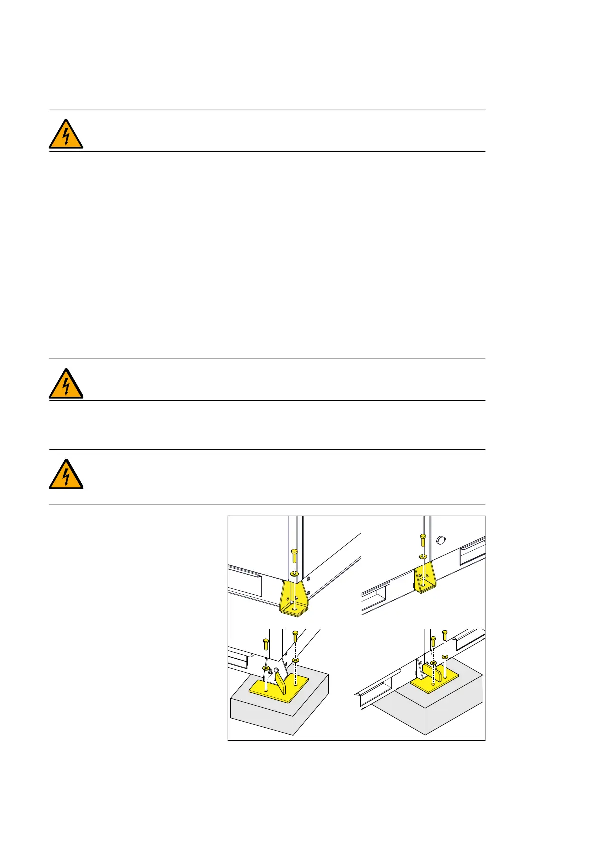
Fastening the inverter
WARNING! Do not fasten the inverter by electric welding. FIMER does not
assume any liability for damages caused by electric welding, as the welding circuit
can damage electronic circuits.
To fasten the cabinet to the
foundation, either use the holes on
the base of the cabinet or use
attachment brackets, if they are
supplied.
The cabinet attachment brackets are
supplied with IEC units. For UL and
CSA units, you must order them
separately.
Use M16 bolts and washers at each
connection point.
Refer to Dimension drawings on
page 117.