82 Electrical installation
DC input cable connection procedure
WARNING! Obey the inverter safety instructions. If you ignore them, injury or
death, or damage to the equipment can occur. If you are not a qualified
electrician, do not do installation or maintenance work.
WARNING! Do the steps in section Electrical safety precautions on page 12
before you start the work.
Refer to Planning the electrical installation on page 57 and Dimension drawings on page
117.
1. Remove the shroud from the input power terminals.
• Remove the screws at the bottom of the outer shroud.
• Pull the outer shroud slightly up and away from the inverter. A suction-cup tool
helps to remove and install the outer shrouds.
• Remove the screws of the inner cover.
• Carefully pull to remove the inner cover. Prevent damage to the sealing gasket.
• Remove the cable lead-throughs.
2. Feed the cables into the cabinet.
3. If it is a shielded cable, connect the shield to the cabinet grounding busbar with a cable
lug.
4. Connect the DC- conductor to terminal DC- and the DC+ conductor to terminal DC+.
5. If there is a separate PE conductor, connect it to the cabinet grounding terminal.
6. Install the cable lead-through and make sure that its ingress protection level matches
the inverter ingress protection level.
7. Install the shroud onto the input power terminals.
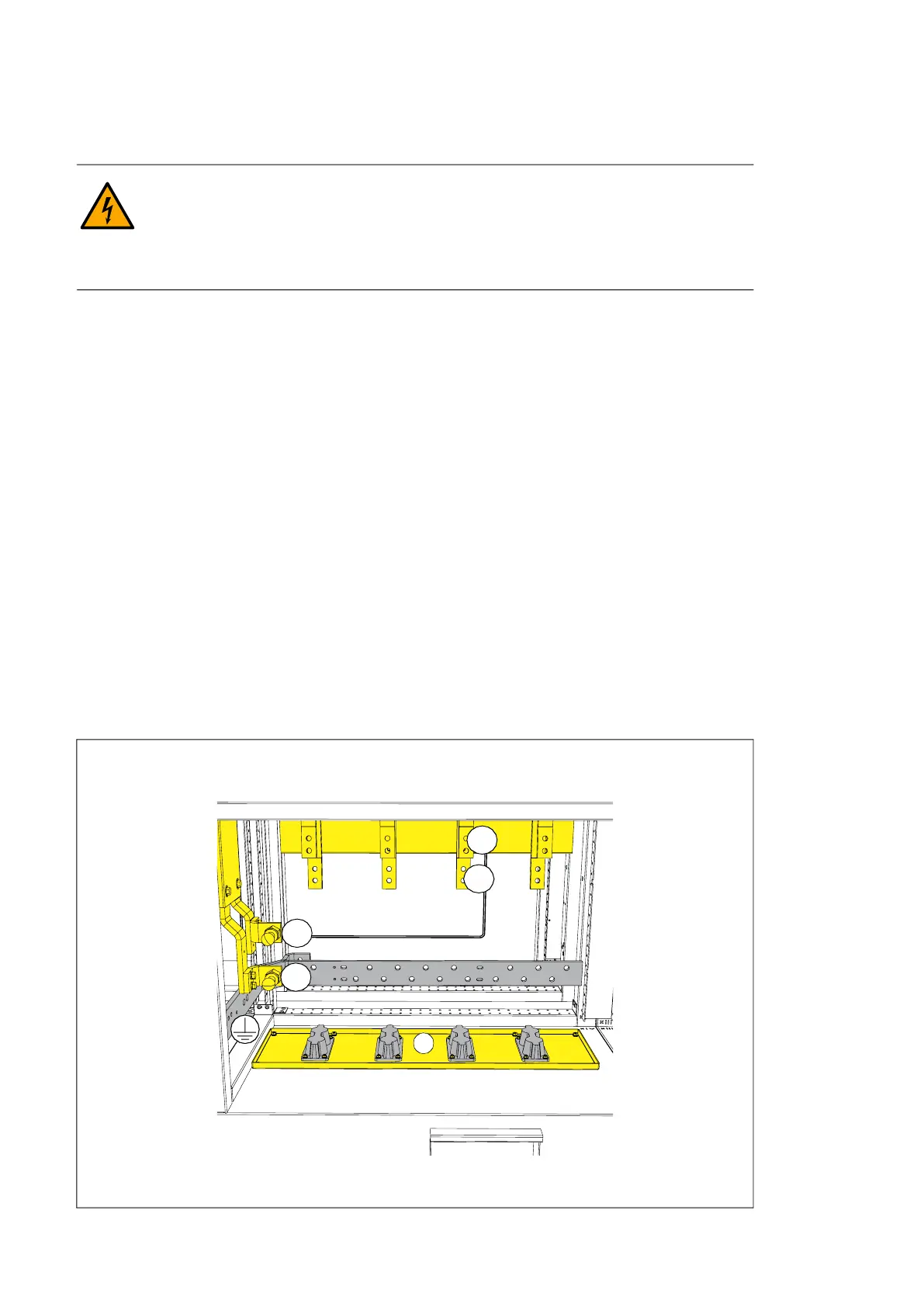
DC input terminals DC-, DC + and the grounding terminal
a) Cable lead-throughs (option H357)
DC-
DC+
a
DC+
DC-