FlyThisSim TouchTrainer® Set-up Guide
Copyright FlyThisSim LLC 2013 Page 23
TouchTrainer® VISX Monitors
Note: This section only applies to TouchTrainer® systems that include the three VISX monitors. If your system does not
include VISX monitors, then your TouchTrainer® is completely assembled and ready for flight. Refer to the assembly
video for more details.
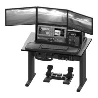
Figure 26: Disassembled VISX System
1) Bolt the left and right members to the central black member using the included M6 lock washers and nuts. Note
that the members are labeled LEFT, CENTER, and RIGHT as per their position while facing the front of the
TouchTrainer®.
Note: It is recommended that the VISX assembly be performed separate from the main touch trainer base to
reduce the risk of damage and improve the ease of assembly.
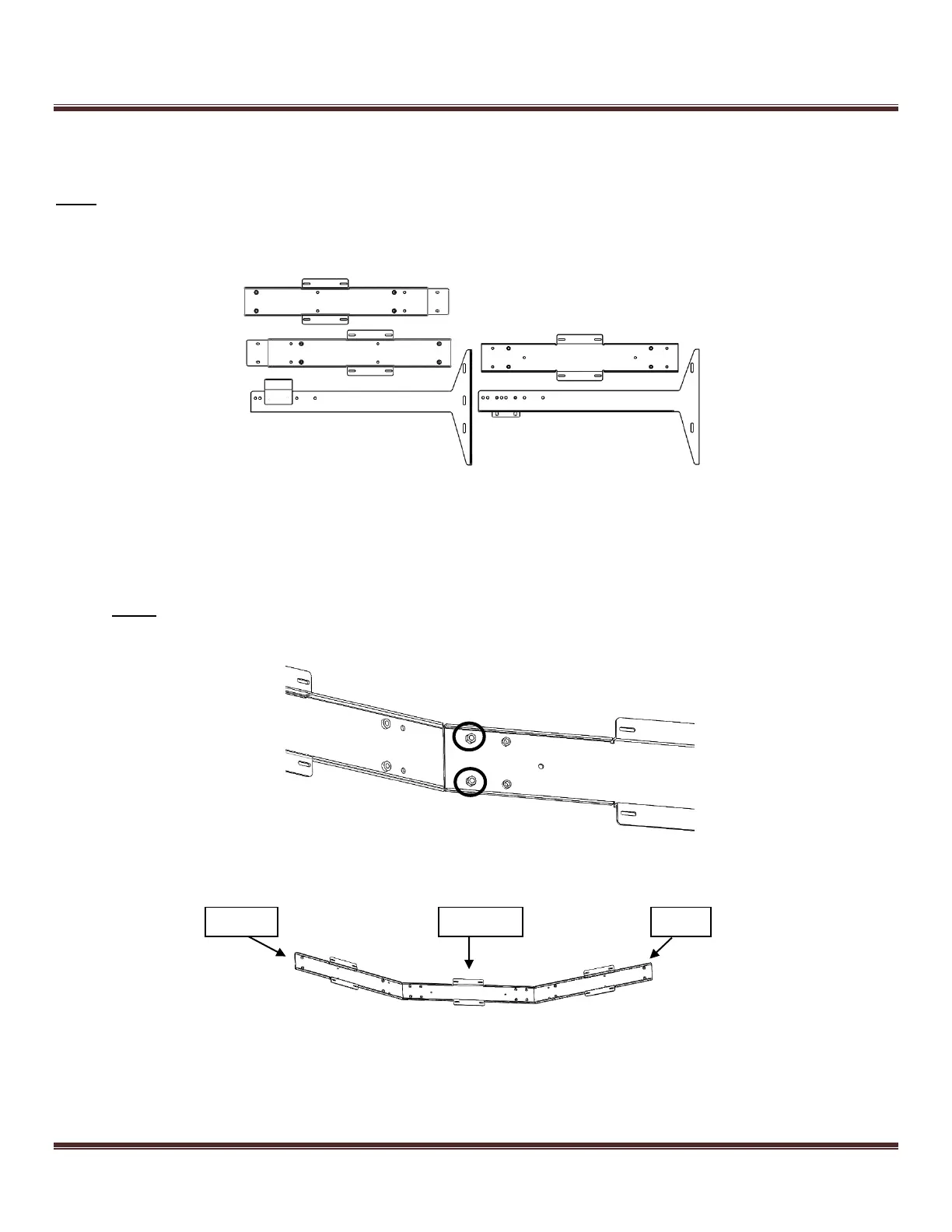
Figure 27: Bolting the left cross-member to the central member
Figure 28: Assembled Cross Members (viewing from the back)