FlyThisSim TouchTrainer® Set-up Guide
Copyright FlyThisSim LLC 2013 Page 25
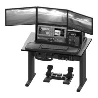
4) Connect the wires from the central junction box to their corresponding plugs, as shown below.
Figure 33: Plugging into the VISX Monitors
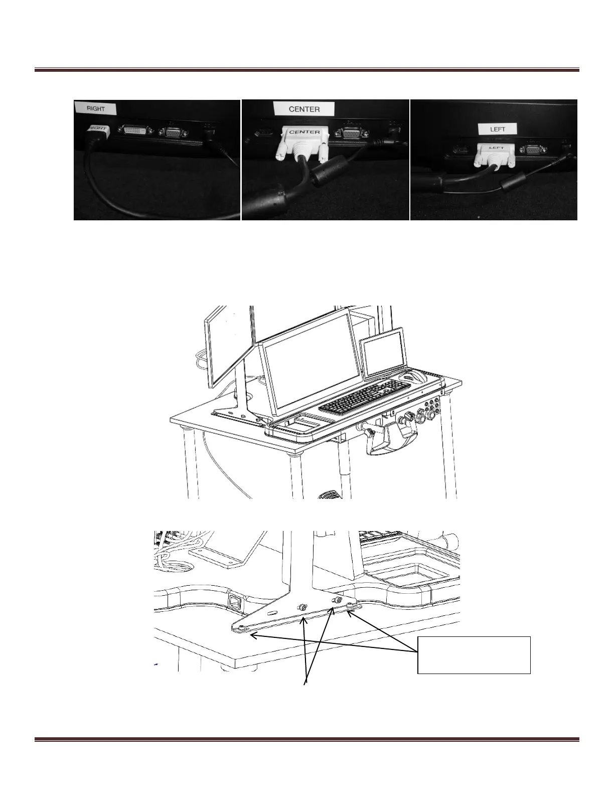
5) Place the entire VISX assembly on the TouchTrainer® base and insert two M6x15 bolts and nylon washers it into
the nutserts located on the sides of the base, through the red uprights. This step may require two people. For
optional added stability, the assembly may be bolted into the table using M6x11 bolts.
Figure 34: Placing the VISX System on the table
Figure 35: Bolting the uprights to the bases
These only bolted if a
Table was purchased