Page 24 Copyright FlyThisSim LLC 2013
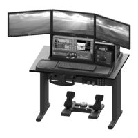
2) Attach the assembled horizontal members to the two vertical uprights via the red flanged brackets, starting with
the left red bracket. This is usually easier to do with the assembly on the ground. Use the same M6 lock washers
and nuts as when assembling the cross members.
Figure 29: Attaching the Cross Members to the Left Upright
Figure 30: Attaching the Assembly to the Right Upright
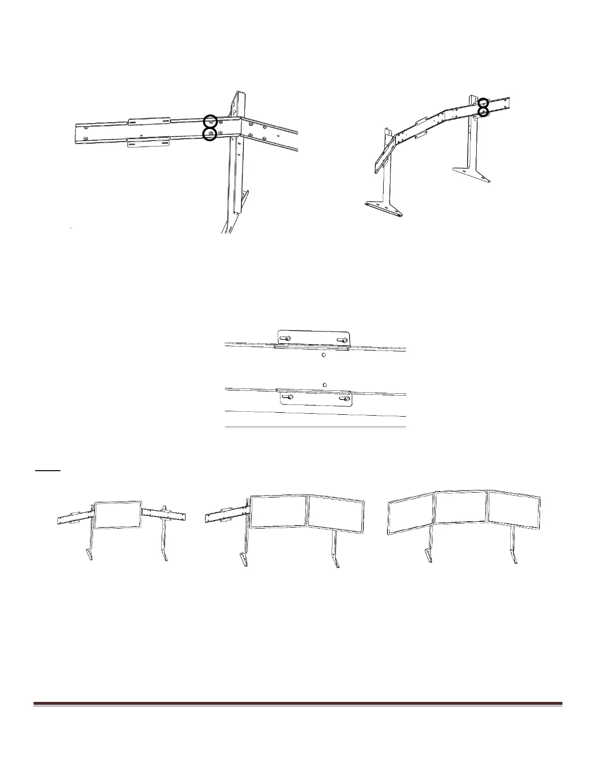
3) Bolt the monitors to the VISX assembly, ensuring the labels are correctly oriented. The monitors come
permanently affixed with four threaded studs. Use the included M4 nuts to secure the monitors to the VISX
assembly. Do not fully tighten the nuts until the monitors are in their final position; leaving the nuts slightly loose
allows the monitors to slide in their slots for easy positioning.
Figure 31: Backside of a bolted VISX Monitor
Note: Ideally, the monitors should be installed in this order: Center, Right, Left.
Figure 32: Attaching the VISX Monitors