Rev 4/2018
17
INSTRUMENTS AND CONTROLS
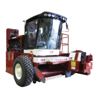
Armrest Control Panel
A. Hydrostatic drive control lever
B. Baler speed switch
C. Tension control
D. Pickup height switch
E. Baler drive engage switch
F. Engine speed adjustment
G. Tension rails open
H. Road/field switch
I. Power port (12VDC)
J. Engine diagnostic gauge (mounted near
floor)
TENSION
RAILS
OPEN
ROAD
STOP
TO
CHANGE
THROTTLE
BALER
ON
OFF
A
B
C
D
E
F
G
H
I
J
Figure 5. Armrest Control Panel
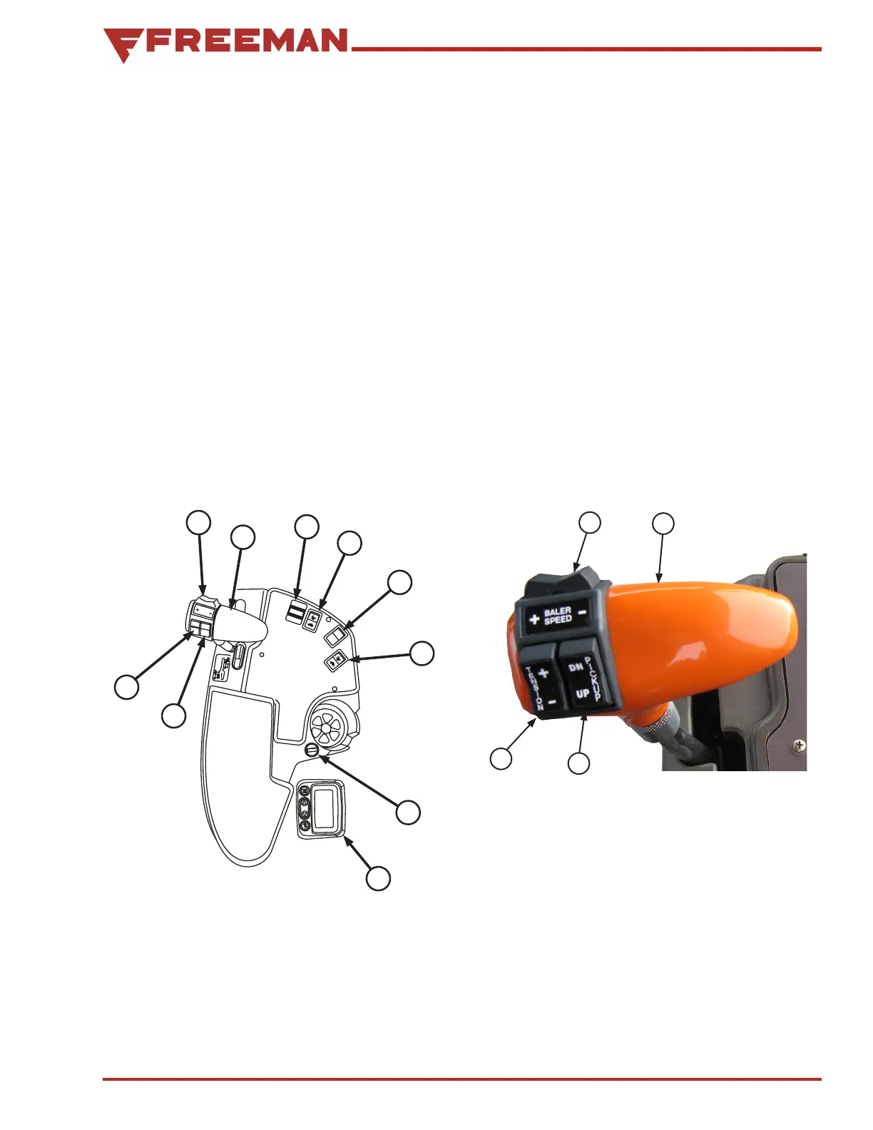
Hydrostatic Drive Control Handle
Functions
The engine must be running to perform any of the
following functions.
Rocker switch (D) raises and lowers the height of
the pickup.
Rocker switch (B) increases or decreases the
speed of the plunger.
Handle (A) controls the hydrostatic drive.
• Move lever to the right and forward to go
forward.
• Move lever to the right and backward to go
backward.
• When the lever is in the left detent, the
automatic parking brake is engaged and the
steering wheel locked. The lever must be in
this position to start the machine.
A
B
C
D
Figure 6. Hydrostatic Drive Control Handle
A. Hydrostatic drive control lever (speed &
direction)
B. Baler speed mode switch (field/road)
C. Tension control
D. Pickup height switch