60
Rev 4/2018
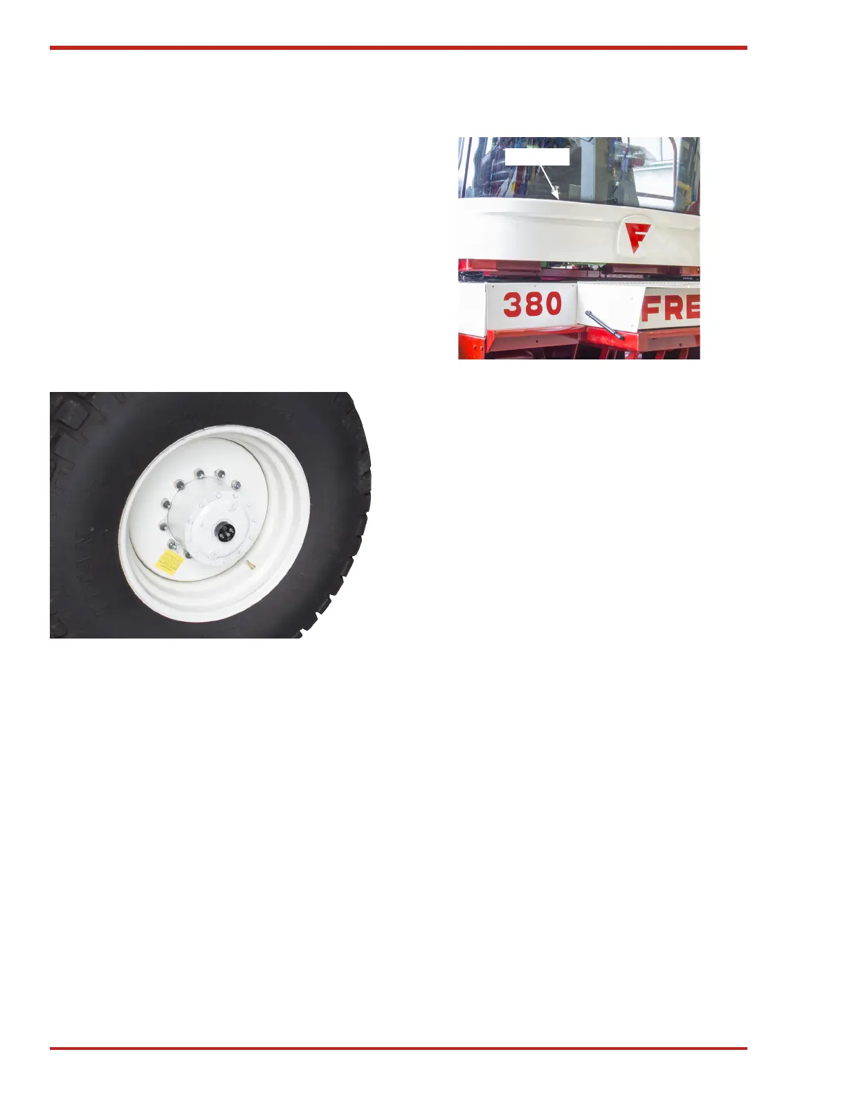
Checking Wheels
IMPORTANT! Maintain proper torque on
wheel hardware according to specifications.
Whenever a wheel is removed, check torque after
one hour of operation. Check cap screws or nuts
every 4 hours until the torque is maintained. There-
after, check torque every 50 hours.
Specification
Frontwheelnuts:torque163N•m(120lb-ft)
Rearwheelcapscrews:torque150N•m(110lb-ft)
Figure 78. Front Wheel
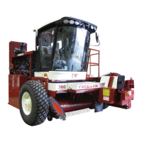
Steering, Hydrostatic Controls and Linkage
Steering and hydrostatic controls are located
behind cowling below front of cab (see Figure 79).
Cowling
Figure 79. Steering & Hydrostatic Controls
Location
Steering controls are combined with forward and
reverse hydrostatic ground drive controls and use
a common linkage (D) (see Figure 80).
IMPORTANT! Any attempt to move the
steering wheel or ground drive lever while
locked will result in damage to the controls
and linkage.
Ground drive cable (A) is connected to the ground
drive control lever in the cab .
Index link (B) keeps the steering and ground drive
synchronized. This allows decreasing or increasing
ground speed without turning the machine. It also
prevents the unit from speeding up or slowing down
when making a turn.
Hydraulic cylinder (C) releases the locking device
when the engine is started and the ground drive
lever is moved out of the neutral park position. The
locking device locks out the steering wheel and the
ground drive control lever.
Steering/hydrostatic linkages (D) are used to move
the control levers on the hydraulic pumps supplying
oil to the left-hand and right-hand hydraulic motors
on the ground drive. The index link (B) controls the
movement of the common linkage.
SETTINGS AND ADJUSTMENTS