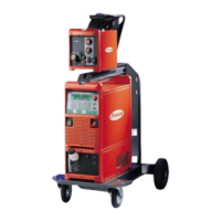
Example ROB 5000 OC:
- X11/5 is not set (= 1)
- X11/6 is not set (= 1)
- X11/7 is set (= 0)
- Frequency range 20 - 200 Hz selected
Job selection
digital (Job/ pro-
gram bit 0-7; ROB
5000/ROB 5000
OC)
Pin Signal ROB 5000 Signal ROB 5000 OC Program bit
X11/1 24 V 0 V 0
X11/2 24 V 0 V 1
X11/3 24 V 0 V 2
X11/4 24 V 0 V 3
X11/5 24 V 0 V 4
X11/6 24 V 0 V 5
X11/7 24 V 0 V 6
X11/8 24 V 0 V 7
NOTE!
The allocations are identical to those in the „Program number“ function. The
choice between the „job number“ and „program number“ functions is made using
mode bits 0 -2.
The “Job number” function is available if “Job mode” was selected using mode bits 0 -2.
When the “Job number” function is used, saved welding parameters are called up using
the number of the corresponding job.
Analog job selec-
tion: System
requirements
System requirements for analog job selection are as follows:
- ROB 5000 / ROB 5000 OC
- Software version ROB 5000/ROB 5000 OC: 1.50.00
- Power source software version: 3.24.70
- RCU 5000i remote control unit software version: 1.07.34
Analog job selec-
tion: activate
Activate analog job selection as follows:
1. - ROB 5000: “Job/Program Select” to “HIGH“
- ROB 5000 OC: “Job/Program Select” to “LOW”
2. Mode bits 0 -2 to “2” = “Job mode”
Analog job selec-
tion: Input
signals
Analog job selection enables job numbers to be selected using the following analog input
signals:
1. Base current
2. Duty cycle
In job mode, the usual functions that these two input signals perform are absent. The two
signals have therefore been given this additional analog job selection function.
IMPORTANT! More information about these two input signals can be found in the “Ana-
log input signals” chapter.
52

 Loading...
