Trouble shooting 9
INDOOR UNIT Error Method:
Standard Wired Remote Error
Indicate or Display:
Indoor Unit : Operation LED 5 Times Blink, Timer LED Flash
Swing LED 1 Time Blink
Outdoor Unit : LED1 Flash, LED6 1Time Blink
ERROR CODE : E : 18
Detective Actuators:
Indoor unit controller PCB circuit
Wired Remote Control
Detective details:
Upon receiving the signal more than 1 time from Wired Remote or other Indoor
unit, but the same signal has not been received more than 1 minute.
Check Point 2 : Check Remote and Controller PCB
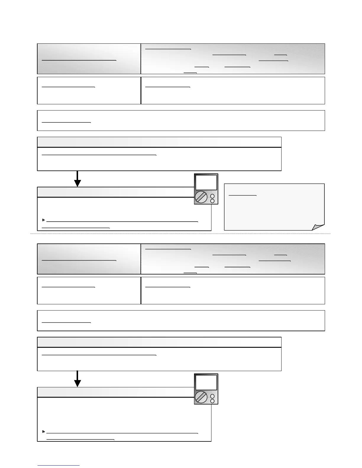
p Check terminal voltage of Control PCB CN17(Power supply for Remote)
If DC12V, Remote Control failure (Control PCB is OK) >>> Replace Remote
If DC0V, Control PCB failure (Remote is OK) >>> Replace Control PCB
In case of re-installation is done due to removed connector or incorrect
wiring, turn on the power again.
Check Point 1 : Check the connection of terminal
After turning off the power, check & correct the followings.
p Indoor Unit - Check the connection of terminal between remote control and Indoor unit, or between Indoor units, and
check if there is a disconnection or short of the cable.
Trouble shooting 10
INDOOR UNIT Error Method:
Standard Wired Token Error
Indicate or Display:
Indoor Unit : Operation LED 5 Times Blink, Timer LED Flash
Swing LED 4 Times Blink
Outdoor Unit : LED1 Flash, LED6 1Time Blink
ERROR CODE : E : 18
Detective Actuators:
Indoor unit Controller PCB circuit
Wired Remote Control
Detective details:
More than 1 time of Token (Communication between wired remote controllers)
is received, but it was not received more than 1 minute.
OK
DC
Forecast of Cause : 1. Terminal connection abnormal 2. Wired Remote Control failure 3. Controller PCB failure
Attention!!
Since Small Wall mount type can not
connect the wired remote, replace
Controller PCB and set up the original
address.
Forecast of Cause : 1. Terminal connection abnormal 2. Mis-setting 3. Wired Remote Control failure 4. Controller PCB failure
Check Point 1 : Check the connection of terminal
After turning off the power, check & correct the followings.
p Indoor Unit - Check the connection of terminal between remote control and Indoor unit, or between Indoor units, and
check if there is a disconnection or short of the cable.
Check Point 2 : Check Setting, Remote and Controller PCB
p Check terminal voltage of Control PCB CN17(Power supply for Remo
p Check the remote controller address of indoor unit and remote
controller DIP SW1-1~3.
te)
If DC12V, Remote Control failure (Control PCB is OK) >>> Replace Remote
If DC0V, Control PCB failure (Remote is OK) >>> Replace Control PCB
In case of re-installation is done due to removed connector or incorrect
wiring, turn on the power again.
OK
DC
06-17

 Loading...